GE 60-806-95R-16Z Installation Instructions - Page 57
Be careful when securing the transformer to an outlet with a metal cover. Hold
 |
UPC - 046188090938
View all GE 60-806-95R-16Z manuals
Add to My Manuals
Save this manual to your list of manuals |
Page 57 highlights
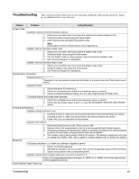
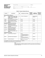
Feature Problem Action/Solution Touchpad display indicates SYSTEM LOW BATTERY. 1. Check that the backup battery is installed correctly and the AC power transformer is plugged in. 2. Measure the incoming AC voltage at the panel terminals 1 and 2. It should read about 16.5 VAC. 3. Remove the backup battery power by disconnecting the red (positive) battery wire. Check for 11.75 to 13.5 VDC battery charging voltage between panel terminal 3 (GND) and the disconnected red battery wire. If the charging voltage is not within range, call Technical Services. 4. Check for 11.75 to 13.5 VDC battery voltage between the backup battery spade lugs. If the battery voltage is not within this range, replace the battery. Note When the panel is running a backup battery test, the reading at the connected battery can range from 11.2 to 13.5 VDC. The panel automatically runs a backup battery test under the following conditions: (1) on initial power-up, (2) during user sensor test, (3) once every minute when backup battery has failed, (4) once every 24 hours at the programmed STIME (UL 98 Options off) or once every 4 hours (UL 98 Options on). With the AC power transformer plugged in, the panel automatically charges the battery. While the battery is charging for the first time it is normal for the system to indicate System battery failure. This can take a number of hours depending on the initial battery charge. Once the battery reaches 12.5 VDC (full charge as measured while in battery test), the condition clears. If the trouble condition persists after 24 hours, replace the backup battery. After you press STATUS, the touchpads flash AC or display AC POWER FAILURE/AC FAILURE. (Panel continues to operate from backup battery.) 1. Check the AC circuit breaker to be sure the circuit is live. 2. Check for proper panel and transformer wiring. 3. Check that the transformer is plugged into a nonswitched outlet and secured with the provided screw. 4. Check that the transformer is supplying AC to the panel. (Transformer internal fuse may be blown.) ! Warning Be careful when securing the transformer to an outlet with a metal cover. Hold the cover tightly in place. You could receive a serious shock if the metal outlet cover drops down onto the prongs of the plug while you are securing the transformer and cover to the outlet box. Phones Loss of dial tone at on-site phones after wiring RJ-31X jack or connecting the DB-8 cord. 1. Wait 2 minutes and try again. The panel may be busy trying to report to the central station. 2. Disconnect the panel DB-8 cord from the RJ-31 jack. If the phone still doesn't work, the system is okay and the problem is in the wiring. 3. Check RJ-31X jack wiring and TELCO block wiring. Replace RJ-31X jack if necessary. 4. Check DB-8 cord connections at the panel and RJ-31X jack. Replace cord if necessary. 5. Perform a phone test after troubleshooting the phone line. Constant dial tone preventing dial-out on premises phones. One or more polarity-sensitive phones exist on-site. Reverse the phone wires connected to the brown and gray wire terminals on the RJ-31X jack. Sirens Piezo sirens connected to SnapCard or onboard (panel) outputs 1 and/or 2 don't produce any alarm sounds. 1. Check for incorrect wiring between siren and panel; correct where necessary. 2. Output has not been configured (set up) to activate sirens. Enter program mode and configure output (see ACCESSORY MODULES-BUS DEVICES-SNAP CARD, or ONBOARD OPTIONS-OUTPUT 1, 2 in the "Programming" section and the tables in Appendix A). Wireless Sensor and Touchpad Batteries Troubleshooting 52
-
 1
1 -
2
-
3
-
4
-
5
-
6
-
7
-
8
-
9
-
10
-
11
-
12
-
13
-
14
-
15
-
16
-
17
-
18
-
19
-
20
-
21
-
22
-
23
-
24
-
25
-
26
-
27
-
28
-
29
-
30
-
31
-
32
-
33
-
34
-
35
-
36
-
37
-
38
-
39
-
40
-
41
-
42
-
43
-
44
-
45
-
46
-
47
-
48
-
49
-
50
-
51
-
 52
52 -
 53
53 -
 54
54 -
 55
55 -
 56
56 -
 57
57 -
 58
58 -
 59
59 -
 60
60 -
 61
61 -
 62
62 -
63
-
64
-
65
-
66
-
67
-
68
-
69
-
70
-
71
-
72
-
73
-
74
-
75
-
76
 |
 |
