HP 1300 Service Manual - Page 103
Fuser assembly, Removing the fuser assembly 1 of 4
 |
UPC - 808736419819
View all HP 1300 manuals
Add to My Manuals
Save this manual to your list of manuals |
Page 103 highlights
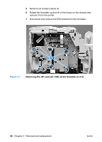
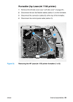
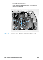
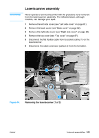
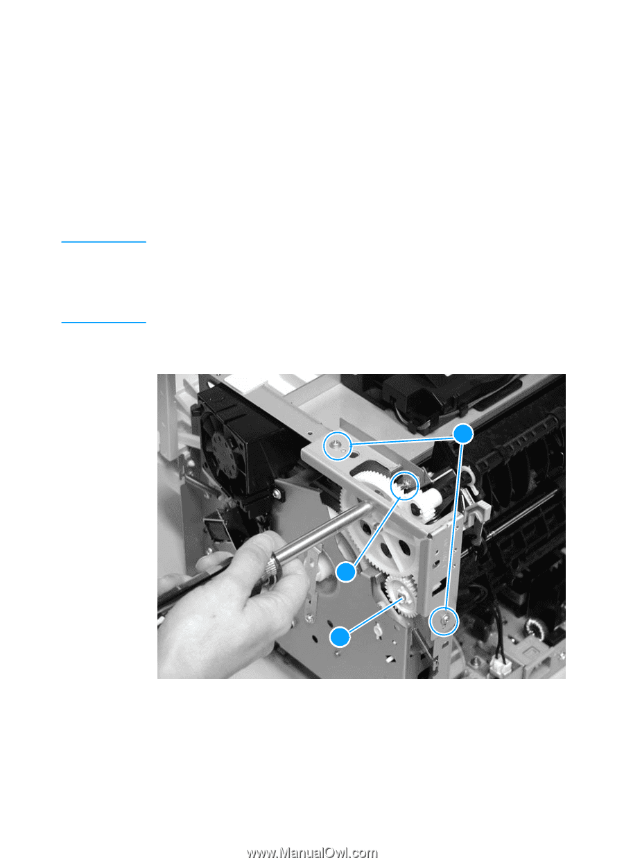
Note Fuser assembly 1 Remove the left side cover (see "Left side cover" on page 81). 2 Remove the back cover (see "Back cover" on page 82). 3 Remove the right side cover (see "Right side cover" on page 84). 4 Remove the top cover (see "Top cover" on page 87). 5 Remove two screws (callout 1) from the right fuser plate. 6 Remove a third screw (callout 2) from behind the large gear on the right fuser plate. You can access the third screw through the holes in the 69Tgear. If you need to realign the 69T gear, you must first remove the pressure roller gear. Release the tab (callout 3) and remove the pressure roller gear from the printer. 7 Remove the bracket. 1 2 3 Figure 46. Removing the fuser assembly (1 of 4) ENWW Internal assemblies 103
-
 1
1 -
2
-
3
-
4
-
5
-
6
-
7
-
8
-
9
-
10
-
11
-
12
-
13
-
14
-
15
-
16
-
17
-
18
-
19
-
20
-
21
-
22
-
23
-
24
-
25
-
26
-
27
-
28
-
29
-
30
-
31
-
32
-
33
-
34
-
35
-
36
-
37
-
38
-
39
-
40
-
41
-
42
-
43
-
44
-
45
-
46
-
47
-
48
-
49
-
50
-
51
-
52
-
53
-
54
-
55
-
56
-
57
-
58
-
59
-
60
-
61
-
62
-
63
-
64
-
65
-
66
-
67
-
68
-
69
-
70
-
71
-
72
-
73
-
74
-
75
-
76
-
77
-
78
-
79
-
80
-
81
-
82
-
83
-
84
-
85
-
86
-
87
-
88
-
89
-
90
-
91
-
92
-
93
-
94
-
95
-
96
-
97
-
 98
98 -
 99
99 -
 100
100 -
 101
101 -
 102
102 -
 103
103 -
 104
104 -
 105
105 -
 106
106 -
 107
107 -
 108
108 -
109
-
110
-
111
-
112
-
113
-
114
-
115
-
116
-
117
-
118
-
119
-
120
-
121
-
122
-
123
-
124
-
125
-
126
-
127
-
128
-
129
-
130
-
131
-
132
-
133
-
134
-
135
-
136
-
137
-
138
-
139
-
140
-
141
-
142
-
143
-
144
-
145
-
146
-
147
-
148
-
149
-
150
-
151
-
152
-
153
-
154
-
155
-
156
-
157
-
158
-
159
-
160
-
161
-
162
-
163
-
164
-
165
-
166
-
167
-
168
-
169
-
170
-
171
-
172
-
173
-
174
-
175
-
176
-
177
-
178
-
179
-
180
-
181
-
182
-
183
-
184
-
185
-
186
-
187
-
188
-
189
-
190
-
191
-
192
-
193
-
194
-
195
-
196
-
197
-
198
-
199
-
200
-
201
-
202
-
203
-
204
-
205
-
206
-
207
-
208
-
209
-
210
-
211
-
212
-
213
-
214
-
215
-
216
-
217
-
218
-
219
-
220
-
221
-
222
 |
 |
ENWW
Internal assemblies
103
Fuser assembly
1
Remove the left side cover (see “Left side cover” on page 81).
2
Remove the back cover (see “Back cover” on page 82).
3
Remove the right side cover (see “Right side cover” on page 84).
4
Remove the top cover (see “Top cover” on page 87).
5
Remove two screws (callout 1) from the right fuser plate.
6
Remove a third screw (callout 2) from behind the large gear on
the right fuser plate.
Note
You can access the third screw through the holes in the 69Tgear.
If you need to realign the 69T gear, you must first remove the pressure
roller gear. Release the tab (callout 3) and remove the pressure roller
gear from the printer.
7
Remove the bracket.
Figure 46.
Removing the fuser assembly (1 of 4)
1
2
3