HP 1300 Service Manual - Page 77
Parts removal order, Removal and replacement strategy
 |
UPC - 808736419819
View all HP 1300 manuals
Add to My Manuals
Save this manual to your list of manuals |
Page 77 highlights
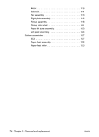
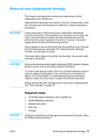
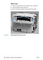
Parts removal order Use the following diagram to determine which parts must be removed before removing other parts: Pickup roller Separation pad Transfer roller Left side cover Formatter Back cover Right side cover Top cover Solenoid Fan assembly (Fuser) Control panel Front cover assembly Right plate assembly (Formatter) Pickup assembly Pickup roller shaft ECU Paper lift plate assembly Paper-feed assembly Motor Left plate assembly Laser/scanner Fuser assembly Output rollers E-label assembly (1300 series only) Note ENWW The fuser and the formatter are listed twice. The fuser must be removed to gain access to the right plate assembly. To remove the fuser only, remove the left side, back, right side, and top covers. The formatter must be removed to gain access to the pickup assembly, the ECU, and the left plate assembly. To remove the formatter only, remove the left side cover. Removal and replacement strategy 77
-
 1
1 -
2
-
3
-
4
-
5
-
6
-
7
-
8
-
9
-
10
-
11
-
12
-
13
-
14
-
15
-
16
-
17
-
18
-
19
-
20
-
21
-
22
-
23
-
24
-
25
-
26
-
27
-
28
-
29
-
30
-
31
-
32
-
33
-
34
-
35
-
36
-
37
-
38
-
39
-
40
-
41
-
42
-
43
-
44
-
45
-
46
-
47
-
48
-
49
-
50
-
51
-
52
-
53
-
54
-
55
-
56
-
57
-
58
-
59
-
60
-
61
-
62
-
63
-
64
-
65
-
66
-
67
-
68
-
69
-
70
-
71
-
 72
72 -
 73
73 -
 74
74 -
 75
75 -
 76
76 -
 77
77 -
 78
78 -
 79
79 -
 80
80 -
 81
81 -
 82
82 -
83
-
84
-
85
-
86
-
87
-
88
-
89
-
90
-
91
-
92
-
93
-
94
-
95
-
96
-
97
-
98
-
99
-
100
-
101
-
102
-
103
-
104
-
105
-
106
-
107
-
108
-
109
-
110
-
111
-
112
-
113
-
114
-
115
-
116
-
117
-
118
-
119
-
120
-
121
-
122
-
123
-
124
-
125
-
126
-
127
-
128
-
129
-
130
-
131
-
132
-
133
-
134
-
135
-
136
-
137
-
138
-
139
-
140
-
141
-
142
-
143
-
144
-
145
-
146
-
147
-
148
-
149
-
150
-
151
-
152
-
153
-
154
-
155
-
156
-
157
-
158
-
159
-
160
-
161
-
162
-
163
-
164
-
165
-
166
-
167
-
168
-
169
-
170
-
171
-
172
-
173
-
174
-
175
-
176
-
177
-
178
-
179
-
180
-
181
-
182
-
183
-
184
-
185
-
186
-
187
-
188
-
189
-
190
-
191
-
192
-
193
-
194
-
195
-
196
-
197
-
198
-
199
-
200
-
201
-
202
-
203
-
204
-
205
-
206
-
207
-
208
-
209
-
210
-
211
-
212
-
213
-
214
-
215
-
216
-
217
-
218
-
219
-
220
-
221
-
222
 |
 |