HP 1300 Service Manual - Page 121
Pickup roller shaft, Removing the pickup roller shaft 1 of 2
 |
UPC - 808736419819
View all HP 1300 manuals
Add to My Manuals
Save this manual to your list of manuals |
Page 121 highlights
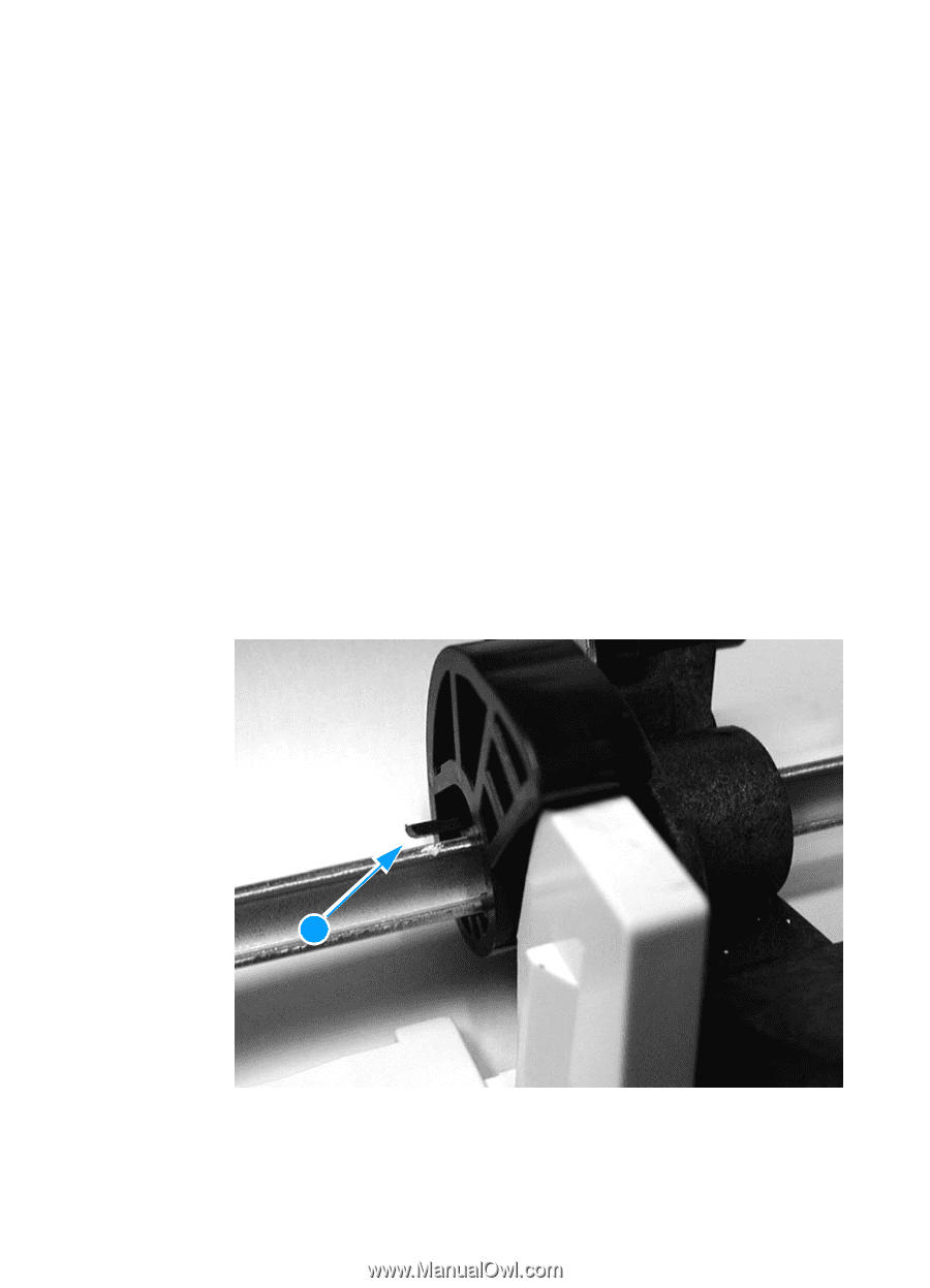
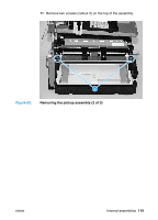
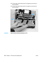
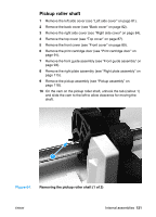
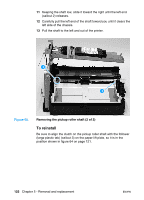
Pickup roller shaft 1 Remove the left side cover (see "Left side cover" on page 81). 2 Remove the back cover (see "Back cover" on page 82). 3 Remove the right side cover (see "Right side cover" on page 84). 4 Remove the top cover (see "Top cover" on page 87). 5 Remove the front cover (see "Front cover" on page 89). 6 Remove the print cartridge door (see "Print cartridge door" on page 91). 7 Remove the front guide assembly (see "Front guide assembly" on page 93). 8 Remove the right plate assembly (see "Right plate assembly" on page 115). 9 Remove the pickup assembly (see "Pickup assembly" on page 118). 10 On the cam on the pickup roller shaft, unhook the tab (callout 1) and slide the cam to the left to allow clearance for moving the shaft. 1 Figure 64. Removing the pickup roller shaft (1 of 2) ENWW Internal assemblies 121
-
 1
1 -
2
-
3
-
4
-
5
-
6
-
7
-
8
-
9
-
10
-
11
-
12
-
13
-
14
-
15
-
16
-
17
-
18
-
19
-
20
-
21
-
22
-
23
-
24
-
25
-
26
-
27
-
28
-
29
-
30
-
31
-
32
-
33
-
34
-
35
-
36
-
37
-
38
-
39
-
40
-
41
-
42
-
43
-
44
-
45
-
46
-
47
-
48
-
49
-
50
-
51
-
52
-
53
-
54
-
55
-
56
-
57
-
58
-
59
-
60
-
61
-
62
-
63
-
64
-
65
-
66
-
67
-
68
-
69
-
70
-
71
-
72
-
73
-
74
-
75
-
76
-
77
-
78
-
79
-
80
-
81
-
82
-
83
-
84
-
85
-
86
-
87
-
88
-
89
-
90
-
91
-
92
-
93
-
94
-
95
-
96
-
97
-
98
-
99
-
100
-
101
-
102
-
103
-
104
-
105
-
106
-
107
-
108
-
109
-
110
-
111
-
112
-
113
-
114
-
115
-
 116
116 -
 117
117 -
 118
118 -
 119
119 -
 120
120 -
 121
121 -
 122
122 -
 123
123 -
 124
124 -
 125
125 -
 126
126 -
127
-
128
-
129
-
130
-
131
-
132
-
133
-
134
-
135
-
136
-
137
-
138
-
139
-
140
-
141
-
142
-
143
-
144
-
145
-
146
-
147
-
148
-
149
-
150
-
151
-
152
-
153
-
154
-
155
-
156
-
157
-
158
-
159
-
160
-
161
-
162
-
163
-
164
-
165
-
166
-
167
-
168
-
169
-
170
-
171
-
172
-
173
-
174
-
175
-
176
-
177
-
178
-
179
-
180
-
181
-
182
-
183
-
184
-
185
-
186
-
187
-
188
-
189
-
190
-
191
-
192
-
193
-
194
-
195
-
196
-
197
-
198
-
199
-
200
-
201
-
202
-
203
-
204
-
205
-
206
-
207
-
208
-
209
-
210
-
211
-
212
-
213
-
214
-
215
-
216
-
217
-
218
-
219
-
220
-
221
-
222
 |
 |