HP 1300 Service Manual - Page 126
Removing the left plate assembly,
 |
UPC - 808736419819
View all HP 1300 manuals
Add to My Manuals
Save this manual to your list of manuals |
Page 126 highlights
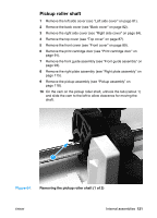
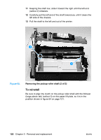
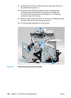
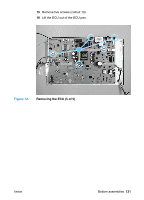
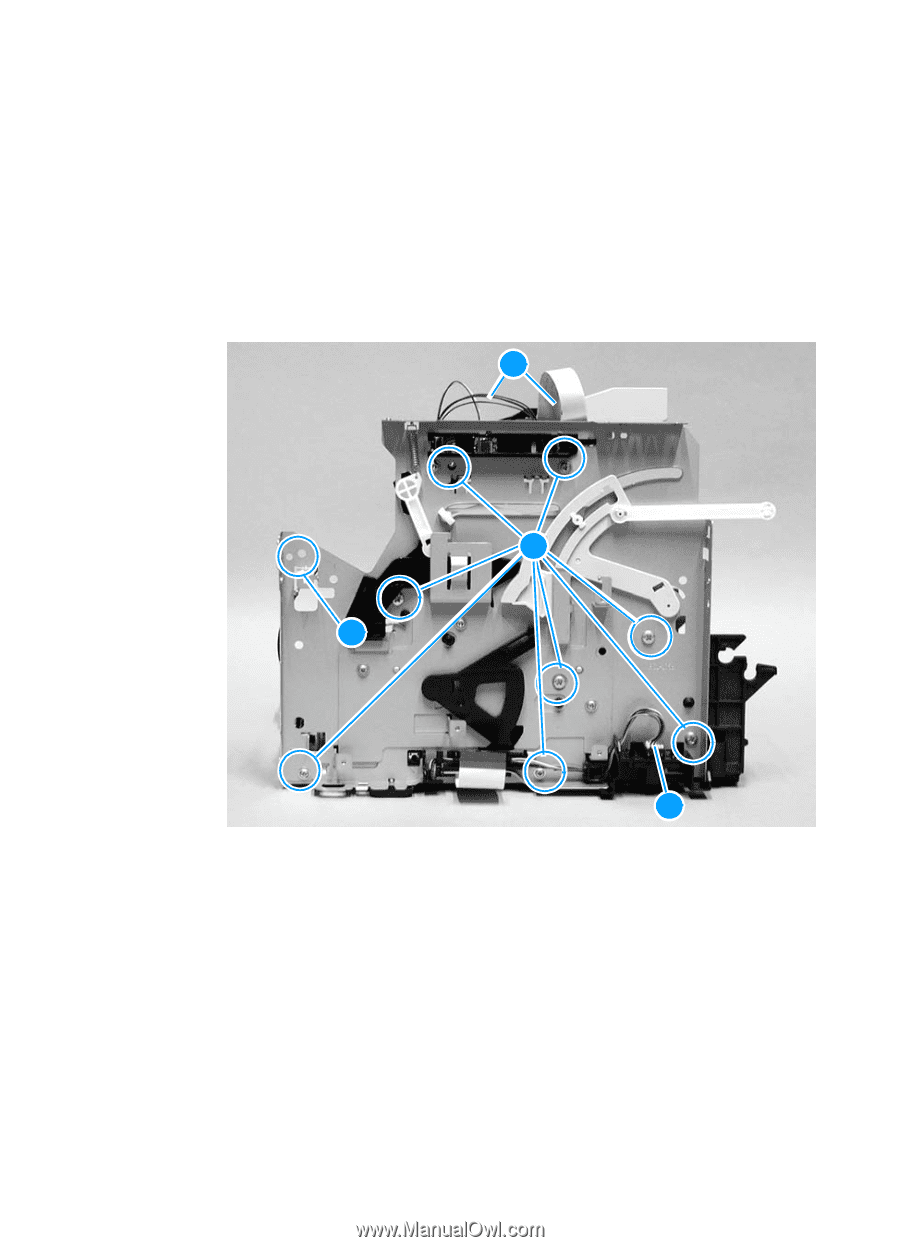
9 Unthread the connector wires and ribbon cable from the top of the printer frame (callout 1). 10 Disconnect the connector (callout 2) from the optional tray connector block at the bottom of the printer, and slide the connector block forward and then straight out. Unthread the connector wires from the stay. 11 Remove eight screws (callout 3). If you have not already removed the fuser, remove the fuser screw (callout 4). 12 Lift the left plate assembly off of the printer. 1 3 4 2 Figure 67. Removing the left plate assembly 126 Chapter 5 - Removal and replacement ENWW
-
 1
1 -
2
-
3
-
4
-
5
-
6
-
7
-
8
-
9
-
10
-
11
-
12
-
13
-
14
-
15
-
16
-
17
-
18
-
19
-
20
-
21
-
22
-
23
-
24
-
25
-
26
-
27
-
28
-
29
-
30
-
31
-
32
-
33
-
34
-
35
-
36
-
37
-
38
-
39
-
40
-
41
-
42
-
43
-
44
-
45
-
46
-
47
-
48
-
49
-
50
-
51
-
52
-
53
-
54
-
55
-
56
-
57
-
58
-
59
-
60
-
61
-
62
-
63
-
64
-
65
-
66
-
67
-
68
-
69
-
70
-
71
-
72
-
73
-
74
-
75
-
76
-
77
-
78
-
79
-
80
-
81
-
82
-
83
-
84
-
85
-
86
-
87
-
88
-
89
-
90
-
91
-
92
-
93
-
94
-
95
-
96
-
97
-
98
-
99
-
100
-
101
-
102
-
103
-
104
-
105
-
106
-
107
-
108
-
109
-
110
-
111
-
112
-
113
-
114
-
115
-
116
-
117
-
118
-
119
-
120
-
 121
121 -
 122
122 -
 123
123 -
 124
124 -
 125
125 -
 126
126 -
 127
127 -
 128
128 -
 129
129 -
 130
130 -
 131
131 -
132
-
133
-
134
-
135
-
136
-
137
-
138
-
139
-
140
-
141
-
142
-
143
-
144
-
145
-
146
-
147
-
148
-
149
-
150
-
151
-
152
-
153
-
154
-
155
-
156
-
157
-
158
-
159
-
160
-
161
-
162
-
163
-
164
-
165
-
166
-
167
-
168
-
169
-
170
-
171
-
172
-
173
-
174
-
175
-
176
-
177
-
178
-
179
-
180
-
181
-
182
-
183
-
184
-
185
-
186
-
187
-
188
-
189
-
190
-
191
-
192
-
193
-
194
-
195
-
196
-
197
-
198
-
199
-
200
-
201
-
202
-
203
-
204
-
205
-
206
-
207
-
208
-
209
-
210
-
211
-
212
-
213
-
214
-
215
-
216
-
217
-
218
-
219
-
220
-
221
-
222
 |
 |
126
Chapter 5 - Removal and replacement
ENWW
9
Unthread the connector wires and ribbon cable from the top of
the printer frame (callout 1).
10
Disconnect the connector (callout 2) from the optional tray
connector block at the bottom of the printer, and slide the
connector block forward and then straight out. Unthread the
connector wires from the stay.
11
Remove eight screws (callout 3). If you have not already removed
the fuser, remove the fuser screw (callout 4).
12
Lift the left plate assembly off of the printer.
Figure 67.
Removing the left plate assembly
1
4
2
3