HP 1300 Service Manual - Page 122
Removing the pickup roller shaft 2 of 2,
 |
UPC - 808736419819
View all HP 1300 manuals
Add to My Manuals
Save this manual to your list of manuals |
Page 122 highlights
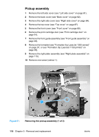
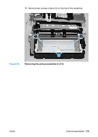
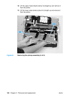
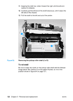
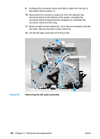
11 Keeping the shaft low, slide it toward the right until the left end (callout 2) releases. 12 Carefully pull the left end of the shaft toward you until it clears the left side of the chassis. 13 Pull the shaft to the left and out of the printer. 2 3 Figure 65. Removing the pickup roller shaft (2 of 2) To reinstall Be sure to align the clutch on the pickup roller shaft with the follower (large plastic tab) (callout 3) on the paper lift plate, so it is in the position shown in figure 64 on page 121. 122 Chapter 5 - Removal and replacement ENWW
-
 1
1 -
2
-
3
-
4
-
5
-
6
-
7
-
8
-
9
-
10
-
11
-
12
-
13
-
14
-
15
-
16
-
17
-
18
-
19
-
20
-
21
-
22
-
23
-
24
-
25
-
26
-
27
-
28
-
29
-
30
-
31
-
32
-
33
-
34
-
35
-
36
-
37
-
38
-
39
-
40
-
41
-
42
-
43
-
44
-
45
-
46
-
47
-
48
-
49
-
50
-
51
-
52
-
53
-
54
-
55
-
56
-
57
-
58
-
59
-
60
-
61
-
62
-
63
-
64
-
65
-
66
-
67
-
68
-
69
-
70
-
71
-
72
-
73
-
74
-
75
-
76
-
77
-
78
-
79
-
80
-
81
-
82
-
83
-
84
-
85
-
86
-
87
-
88
-
89
-
90
-
91
-
92
-
93
-
94
-
95
-
96
-
97
-
98
-
99
-
100
-
101
-
102
-
103
-
104
-
105
-
106
-
107
-
108
-
109
-
110
-
111
-
112
-
113
-
114
-
115
-
116
-
 117
117 -
 118
118 -
 119
119 -
 120
120 -
 121
121 -
 122
122 -
 123
123 -
 124
124 -
 125
125 -
 126
126 -
 127
127 -
128
-
129
-
130
-
131
-
132
-
133
-
134
-
135
-
136
-
137
-
138
-
139
-
140
-
141
-
142
-
143
-
144
-
145
-
146
-
147
-
148
-
149
-
150
-
151
-
152
-
153
-
154
-
155
-
156
-
157
-
158
-
159
-
160
-
161
-
162
-
163
-
164
-
165
-
166
-
167
-
168
-
169
-
170
-
171
-
172
-
173
-
174
-
175
-
176
-
177
-
178
-
179
-
180
-
181
-
182
-
183
-
184
-
185
-
186
-
187
-
188
-
189
-
190
-
191
-
192
-
193
-
194
-
195
-
196
-
197
-
198
-
199
-
200
-
201
-
202
-
203
-
204
-
205
-
206
-
207
-
208
-
209
-
210
-
211
-
212
-
213
-
214
-
215
-
216
-
217
-
218
-
219
-
220
-
221
-
222
 |
 |
122
Chapter 5 - Removal and replacement
ENWW
11
Keeping the shaft low, slide it toward the right until the left end
(callout 2) releases.
12
Carefully pull the left end of the shaft toward you until it clears the
left side of the chassis.
13
Pull the shaft to the left and out of the printer.
Figure 65.
Removing the pickup roller shaft (2 of 2)
To reinstall
Be sure to align the clutch on the pickup roller shaft with the follower
(large plastic tab) (callout 3) on the paper lift plate, so it is in the
position shown in figure 64 on page 121.
2
3