HP 1300 Service Manual - Page 110
Motor, Removing the motor
 |
UPC - 808736419819
View all HP 1300 manuals
Add to My Manuals
Save this manual to your list of manuals |
Page 110 highlights
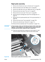
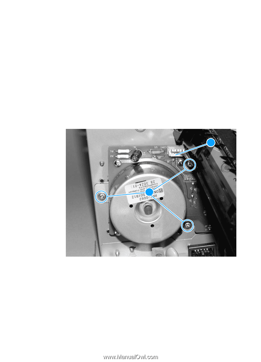
Motor 1 Remove the left side cover (see "Left side cover" on page 81). 2 Remove the back cover (see "Back cover" on page 82). 3 Remove the right side cover (see "Right side cover" on page 84). 4 Remove the fuser assembly (see "Fuser assembly" on page 103). 5 Remove the ECU pan (see "ECU" on page 127). 6 Disconnect the motor cable connector (callout 1) above the motor. 7 Remove the three screws (callout 2) from the motor and lift the motor out of the printer. 1 2 Figure 53. Removing the motor To reinstall Make sure that the motor is in the correct position. The connector should be above and to the back of the motor. 110 Chapter 5 - Removal and replacement ENWW
-
 1
1 -
2
-
3
-
4
-
5
-
6
-
7
-
8
-
9
-
10
-
11
-
12
-
13
-
14
-
15
-
16
-
17
-
18
-
19
-
20
-
21
-
22
-
23
-
24
-
25
-
26
-
27
-
28
-
29
-
30
-
31
-
32
-
33
-
34
-
35
-
36
-
37
-
38
-
39
-
40
-
41
-
42
-
43
-
44
-
45
-
46
-
47
-
48
-
49
-
50
-
51
-
52
-
53
-
54
-
55
-
56
-
57
-
58
-
59
-
60
-
61
-
62
-
63
-
64
-
65
-
66
-
67
-
68
-
69
-
70
-
71
-
72
-
73
-
74
-
75
-
76
-
77
-
78
-
79
-
80
-
81
-
82
-
83
-
84
-
85
-
86
-
87
-
88
-
89
-
90
-
91
-
92
-
93
-
94
-
95
-
96
-
97
-
98
-
99
-
100
-
101
-
102
-
103
-
104
-
 105
105 -
 106
106 -
 107
107 -
 108
108 -
 109
109 -
 110
110 -
 111
111 -
 112
112 -
 113
113 -
 114
114 -
 115
115 -
116
-
117
-
118
-
119
-
120
-
121
-
122
-
123
-
124
-
125
-
126
-
127
-
128
-
129
-
130
-
131
-
132
-
133
-
134
-
135
-
136
-
137
-
138
-
139
-
140
-
141
-
142
-
143
-
144
-
145
-
146
-
147
-
148
-
149
-
150
-
151
-
152
-
153
-
154
-
155
-
156
-
157
-
158
-
159
-
160
-
161
-
162
-
163
-
164
-
165
-
166
-
167
-
168
-
169
-
170
-
171
-
172
-
173
-
174
-
175
-
176
-
177
-
178
-
179
-
180
-
181
-
182
-
183
-
184
-
185
-
186
-
187
-
188
-
189
-
190
-
191
-
192
-
193
-
194
-
195
-
196
-
197
-
198
-
199
-
200
-
201
-
202
-
203
-
204
-
205
-
206
-
207
-
208
-
209
-
210
-
211
-
212
-
213
-
214
-
215
-
216
-
217
-
218
-
219
-
220
-
221
-
222
 |
 |
110
Chapter 5 - Removal and replacement
ENWW
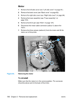
Motor
1
Remove the left side cover (see “Left side cover” on page 81).
2
Remove the back cover (see “Back cover” on page 82).
3
Remove the right side cover (see “Right side cover” on page 84).
4
Remove the fuser assembly (see “Fuser assembly” on
page 103).
5
Remove the ECU pan (see “ECU” on page 127).
6
Disconnect the motor cable connector (callout 1) above the
motor.
7
Remove the three screws (callout 2) from the motor and lift the
motor out of the printer.
Figure 53.
Removing the motor
To reinstall
Make sure that the motor is in the correct position. The connector
should be above and to the back of the motor.
1
2