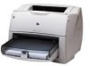
HP 1300 Service Manual - Page 75
Removal and replacement strategy, Required tools
 |
UPC - 808736419819
View all HP 1300 manuals
Add to My Manuals
Save this manual to your list of manuals |
Page 75 highlights
Removal and replacement strategy WARNING! This chapter documents the removal and replacement of field replaceable units (FRUs) only. Replacement is generally the reverse of removal. Occasionally, notes are included to provide directions for difficult or critical replacement procedures. Unplug the power cord from the power outlet before attempting to service the printer. If this warning is not followed, severe injury can result. Certain functional checks during troubleshooting must be performed with power supplied to the printer. However, the power supply should be disconnected during removal. Never operate or service the printer with the protective cover removed from the laser/scanner assembly. The reflected beam, although invisible, can damage your eyes. The sheet metal edges of the printer can be sharp. Use caution when working on the printer. CAUTION Some printer parts are electrostatic discharge (ESD) sensitive. Always perform service work at an ESD-protected workstation. To install a self-tapping screw, first turn it counterclockwise to align it with the existing thread pattern, then carefully turn it clockwise to tighten. Do not overtighten. If a self-tapping screw-hole becomes stripped, repair the screw-hole or replace the affected assembly. Always remove the print cartridge before removing or replacing parts. See "Print cartridge" on page 76. CAUTION Required tools z #2 Phillips-head screwdriver with magnetic tip z Small flatblade screwdriver z Needle nose pliers z ESD mat z Penlight A PoziDriv screwdriver will damage screw heads on the printer. Use a #2 Phillips-head screwdriver. ENWW Removal and replacement strategy 75
-
 1
1 -
2
-
3
-
4
-
5
-
6
-
7
-
8
-
9
-
10
-
11
-
12
-
13
-
14
-
15
-
16
-
17
-
18
-
19
-
20
-
21
-
22
-
23
-
24
-
25
-
26
-
27
-
28
-
29
-
30
-
31
-
32
-
33
-
34
-
35
-
36
-
37
-
38
-
39
-
40
-
41
-
42
-
43
-
44
-
45
-
46
-
47
-
48
-
49
-
50
-
51
-
52
-
53
-
54
-
55
-
56
-
57
-
58
-
59
-
60
-
61
-
62
-
63
-
64
-
65
-
66
-
67
-
68
-
69
-
 70
70 -
 71
71 -
 72
72 -
 73
73 -
 74
74 -
 75
75 -
 76
76 -
 77
77 -
 78
78 -
 79
79 -
 80
80 -
81
-
82
-
83
-
84
-
85
-
86
-
87
-
88
-
89
-
90
-
91
-
92
-
93
-
94
-
95
-
96
-
97
-
98
-
99
-
100
-
101
-
102
-
103
-
104
-
105
-
106
-
107
-
108
-
109
-
110
-
111
-
112
-
113
-
114
-
115
-
116
-
117
-
118
-
119
-
120
-
121
-
122
-
123
-
124
-
125
-
126
-
127
-
128
-
129
-
130
-
131
-
132
-
133
-
134
-
135
-
136
-
137
-
138
-
139
-
140
-
141
-
142
-
143
-
144
-
145
-
146
-
147
-
148
-
149
-
150
-
151
-
152
-
153
-
154
-
155
-
156
-
157
-
158
-
159
-
160
-
161
-
162
-
163
-
164
-
165
-
166
-
167
-
168
-
169
-
170
-
171
-
172
-
173
-
174
-
175
-
176
-
177
-
178
-
179
-
180
-
181
-
182
-
183
-
184
-
185
-
186
-
187
-
188
-
189
-
190
-
191
-
192
-
193
-
194
-
195
-
196
-
197
-
198
-
199
-
200
-
201
-
202
-
203
-
204
-
205
-
206
-
207
-
208
-
209
-
210
-
211
-
212
-
213
-
214
-
215
-
216
-
217
-
218
-
219
-
220
-
221
-
222
 |
 |