HP 9000 rp4410-4 Installation Guide, Sixth Edition - HP 9000 rp4410/rp4440 - Page 25
Control Panel, Table 1-3, Control Panel LED Definitions, LED/ Button, State, Flash Rate
 |
View all HP 9000 rp4410-4 manuals
Add to My Manuals
Save this manual to your list of manuals |
Page 25 highlights
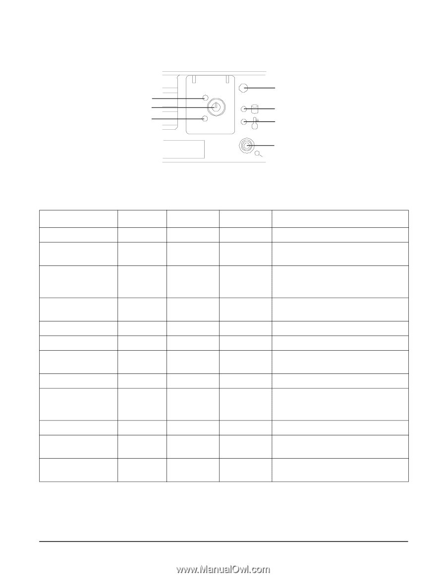
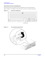
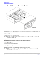
Figure 1-8 Control Panel Power LED Power Button TOC/NMI Button Installing the System Installing Additional Components System LED Disk LED Thermal LED Locator Button/LED Table 1-3 and Table 1-4 list the control panel LED and the switch and button LED status and descriptions. Table 1-3 Control Panel LED Definitions LED/ Button State Flash Rate Color Description System LED System LED System LED Running Booting Attention Steady Flashing at 0.5 Hz Flashing at 1 Hz Green Green Yellow System LED System LED Power LED Power LED Power LED Disk LED Fault Off On On Off Thermal LED Thermal LED OK Warning Locator Button/LED Flashing at 2 Hz Off Steady Flashing at 1 Hz Off Flashing at rate of disk activity Steady Flashing at 1 Hz Flashing at 1 Hz Red N/A Green Yellow Off Green Green Yellow Blue System normal; OS up and running. OS booting or at BCH. Warning-System needs attention. Redundancy lost, component failure pending. Hard fault. System halted. System off. Power normal. Housekeeping voltage present. Power off. Disk activity. Thermal OK. Thermal warning. System locator LED can be remotely or locally activated and deactivated. Chapter 1 25
-
 1
1 -
2
-
3
-
4
-
5
-
6
-
7
-
8
-
9
-
10
-
11
-
12
-
13
-
14
-
15
-
16
-
17
-
18
-
19
-
 20
20 -
 21
21 -
 22
22 -
 23
23 -
 24
24 -
 25
25 -
 26
26 -
 27
27 -
 28
28 -
 29
29 -
 30
30 -
31
-
32
-
33
-
34
-
35
-
36
-
37
-
38
-
39
-
40
-
41
-
42
-
43
-
44
-
45
-
46
-
47
-
48
-
49
-
50
-
51
-
52
-
53
-
54
-
55
-
56
-
57
-
58
-
59
-
60
-
61
-
62
-
63
-
64
-
65
-
66
-
67
-
68
-
69
-
70
-
71
-
72
-
73
-
74
-
75
-
76
-
77
-
78
-
79
-
80
-
81
-
82
-
83
-
84
-
85
-
86
-
87
-
88
-
89
-
90
-
91
-
92
-
93
-
94
-
95
-
96
-
97
-
98
-
99
-
100
-
101
-
102
-
103
 |
 |