HP 9000 rp4410-4 Installation Guide, Sixth Edition - HP 9000 rp4410/rp4440 - Page 29
Front and Top Covers, Replacing the Front Bezel, Removing the Front Cover, Step 1.
 |
View all HP 9000 rp4410-4 manuals
Add to My Manuals
Save this manual to your list of manuals |
Page 29 highlights
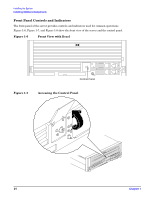
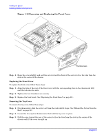
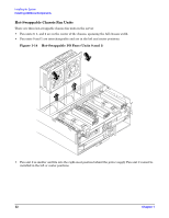
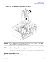
Installing the System Installing Additional Components The front control panel access door is on the bezel. Opening the control panel door provides access to the following components: • Power button • System LEDs Replacing the Front Bezel To replace the front bezel, hold the bezel in mounting position and push the bezel straight into the chassis until it snaps into place. Front and Top Covers CAUTION Do not operate the server without the front and top covers in place. Operation of the server without the front and top covers in place makes the server susceptible to electromagnetic interference (EMI) and overheating problems that result in system failure. Observe all electrostatic discharge (ESD) safety precautions before attempting this procedure. Failure to follow ESD safety precautions can result in damage to the server. NOTE When the front or top cover is removed, the chassis fan units increase to high speed to assist cooling. When the top cover is replaced at the end of the operation, the chassis fans return to normal speed. Removing the Front Cover CAUTION Power the server off prior to removing the front cover. All components accessible behind the front cover are cold-swappable and require power to be off. To remove the front cover, follow these steps: Step 1. If rack-mounted, slide the server out from the rack until it stops. (See "Extend the Server from the Rack" on page 22.) Step 2. Remove the front bezel. (See "Removing the Front Bezel" on page 28.) Step 3. Loosen the four captive thumbscrews that hold the front cover in place. Chapter 1 29
-
 1
1 -
2
-
3
-
4
-
5
-
6
-
7
-
8
-
9
-
10
-
11
-
12
-
13
-
14
-
15
-
16
-
17
-
18
-
19
-
20
-
21
-
22
-
23
-
 24
24 -
 25
25 -
 26
26 -
 27
27 -
 28
28 -
 29
29 -
 30
30 -
 31
31 -
 32
32 -
 33
33 -
 34
34 -
35
-
36
-
37
-
38
-
39
-
40
-
41
-
42
-
43
-
44
-
45
-
46
-
47
-
48
-
49
-
50
-
51
-
52
-
53
-
54
-
55
-
56
-
57
-
58
-
59
-
60
-
61
-
62
-
63
-
64
-
65
-
66
-
67
-
68
-
69
-
70
-
71
-
72
-
73
-
74
-
75
-
76
-
77
-
78
-
79
-
80
-
81
-
82
-
83
-
84
-
85
-
86
-
87
-
88
-
89
-
90
-
91
-
92
-
93
-
94
-
95
-
96
-
97
-
98
-
99
-
100
-
101
-
102
-
103
 |
 |
