HP 9000 rp4410-4 Installation Guide, Sixth Edition - HP 9000 rp4410/rp4440 - Page 58
Slot ID Numbering, PCI/PCI-X Slot Locations and Configurations, are not hot-pluggable
 |
View all HP 9000 rp4410-4 manuals
Add to My Manuals
Save this manual to your list of manuals |
Page 58 highlights
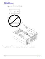
Installing the System Installing Additional Components PCI/PCI-X Slot Locations and Configurations PCI/PCI-X slots are numbered from 1 through 8 in the server as shown in Figure 1-32. Figure 1-32 Slot ID Numbering PCI-X Bus 1 PCI-X Bus 2 PCI-X Bus 3 PCI-X Bus 4 PCI-X Bus 5 12 34 56 78 PCI Slot ID Numbers Amber Attention LEDs Green Power LEDs Core I/O PCI-X Public I/O Hot-pluggable PCI-X Amber Attention LEDs The following describes configuration requirements for slots 1 through 8: • PCI slots 1 and 2 are dedicated for use by the core I/O cards: SCSI HBA card in slot 1 and Gigabit Ethernet LAN card in slot 2. Slots 1 and 2 are not hot-pluggable. Additional PCI/PCI-X expansion cards must not be placed in slots 1 or 2. • Slots 3 and 4 share a PCI bus, and slots 5 and 6 share a PCI bus. The maximum capability of each of the shared slots is PCI/PCI-X 66 MHz. If a PCI/PCI-X 133 MHz card is placed in a shared slot, the PCI/PCI-X 133 MHz card runs at a maximum of 66 MHz. If different modes (PCI versus PCI-X) or slower speeds (33 MHz) are used, the slot automatically downgrades to accept the change. 58 Chapter 1
-
 1
1 -
2
-
3
-
4
-
5
-
6
-
7
-
8
-
9
-
10
-
11
-
12
-
13
-
14
-
15
-
16
-
17
-
18
-
19
-
20
-
21
-
22
-
23
-
24
-
25
-
26
-
27
-
28
-
29
-
30
-
31
-
32
-
33
-
34
-
35
-
36
-
37
-
38
-
39
-
40
-
41
-
42
-
43
-
44
-
45
-
46
-
47
-
48
-
49
-
50
-
51
-
52
-
 53
53 -
 54
54 -
 55
55 -
 56
56 -
 57
57 -
 58
58 -
 59
59 -
 60
60 -
 61
61 -
 62
62 -
 63
63 -
64
-
65
-
66
-
67
-
68
-
69
-
70
-
71
-
72
-
73
-
74
-
75
-
76
-
77
-
78
-
79
-
80
-
81
-
82
-
83
-
84
-
85
-
86
-
87
-
88
-
89
-
90
-
91
-
92
-
93
-
94
-
95
-
96
-
97
-
98
-
99
-
100
-
101
-
102
-
103
 |
 |
