HP 9000 rp4410-4 Installation Guide, Sixth Edition - HP 9000 rp4410/rp4440 - Page 71
Installing SCSI Cable B to the SCSI Adapter Board, Replacing the Removed Modules, Step 1.
 |
View all HP 9000 rp4410-4 manuals
Add to My Manuals
Save this manual to your list of manuals |
Page 71 highlights
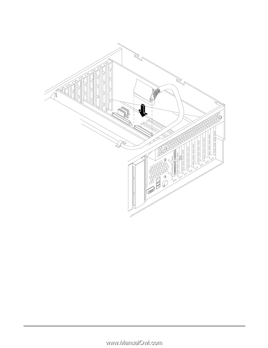
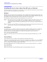
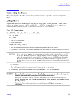
Installing the System Installing Additional Components Figure 1-39 Installing SCSI Cable B to the SCSI Adapter Board Replacing the Removed Modules To return the server to operational configuration, follow these steps: Step 1. Replace the processor extender board. (See "Replacing the Processor Extender Board" on page 51.) Step 2. Replace the memory extender board. (See "Replacing the Memory Extender Board" on page 56.) Step 3. Replace the top cover. (See "Replacing the Top Cover" on page 31.) Step 4. Replace the front cover. (See "Replacing the Front Cover" on page 30.) Step 5. Replace the front bezel. (See "Replacing the Front Bezel" on page 29.) Step 6. If rack-mounted, slide the server back into the rack until it stops. (See "Installing the Server Into a Rack, Non-HP rack, or Pedestal" on page 72.) Chapter 1 71
-
 1
1 -
2
-
3
-
4
-
5
-
6
-
7
-
8
-
9
-
10
-
11
-
12
-
13
-
14
-
15
-
16
-
17
-
18
-
19
-
20
-
21
-
22
-
23
-
24
-
25
-
26
-
27
-
28
-
29
-
30
-
31
-
32
-
33
-
34
-
35
-
36
-
37
-
38
-
39
-
40
-
41
-
42
-
43
-
44
-
45
-
46
-
47
-
48
-
49
-
50
-
51
-
52
-
53
-
54
-
55
-
56
-
57
-
58
-
59
-
60
-
61
-
62
-
63
-
64
-
65
-
 66
66 -
 67
67 -
 68
68 -
 69
69 -
 70
70 -
 71
71 -
 72
72 -
 73
73 -
 74
74 -
 75
75 -
 76
76 -
77
-
78
-
79
-
80
-
81
-
82
-
83
-
84
-
85
-
86
-
87
-
88
-
89
-
90
-
91
-
92
-
93
-
94
-
95
-
96
-
97
-
98
-
99
-
100
-
101
-
102
-
103
 |
 |