HP 9000 rp4410-4 Installation Guide, Sixth Edition - HP 9000 rp4410/rp4440 - Page 96
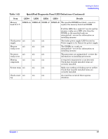
Table 1-22, QuickFind Diagnostic Panel LED Definitions, Front Control Panel LED Definitions Continued
 |
View all HP 9000 rp4410-4 manuals
Add to My Manuals
Save this manual to your list of manuals |
Page 96 highlights
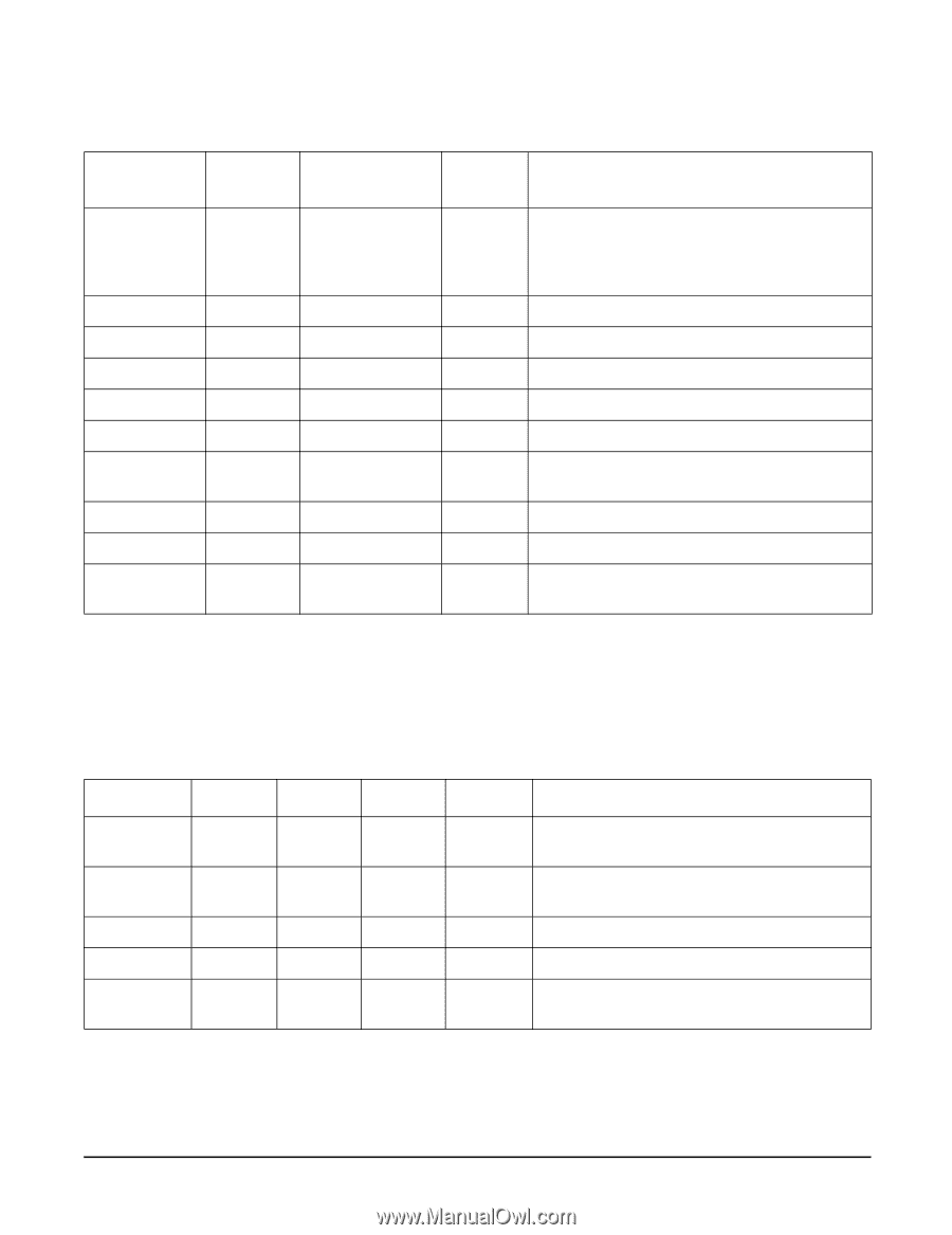
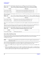
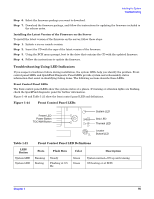
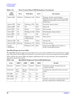
Installing the System Troubleshooting Table 1-21 Front Control Panel LED Definitions (Continued) LED/ Button System LED State Flash Rate Color Attention Flashing at 1 Hz Yellow System LED System LED Power LED Power LED Power LED Disk LED Fault Off On On Off Thermal LED OK Thermal LED Warning Locator LED/button Flashing at 2 Hz Red Off N/A Steady Green Flashing at 1 Hz Yellow Off Off Flashing at rate Green of disk activity Steady Green Flashing at 1 Hz Yellow Flashing at 1 Hz Blue Description Warning-System needs attention. Redundancy lost, component failure pending. (Additional information can be found in the System Log). Hard fault, system halted. System off. Power normal. Housekeeping voltage present. Power off. Disk activity. Thermal OK. Thermal warning. System locator LED can be remotely or locally activated/deactivated. QuickFind Diagnostic Panel LEDs The QuickFind diagnostic panel is located under the top cover and is attached to the top of the power supply cage. This panel contains LEDs that illuminate to show the status of associated components and assemblies. Table 1-22 lists the various LEDs and display combinations that you may encounter, and recommends the appropriate maintenance action. Table 1-22 QuickFind Diagnostic Panel LED Definitions Item Processor LED 0 Socket 0 Subsystem CPU board I/O VRM n/a CPU VRM n/a Fan module 0 LED1 Socket 1 Memory board n/a n/a 1 LED2 LED3 Socket 2 Socket 3 I/O board n/a n/a n/a n/a n/a 2 n/a Details Check that recently installed items are correctly installed. Check that the indicated board is correctly seated. n/a n/a Check for a fan that is not functioning. Look for loose connections or missing items. 96 Chapter 1
-
 1
1 -
2
-
3
-
4
-
5
-
6
-
7
-
8
-
9
-
10
-
11
-
12
-
13
-
14
-
15
-
16
-
17
-
18
-
19
-
20
-
21
-
22
-
23
-
24
-
25
-
26
-
27
-
28
-
29
-
30
-
31
-
32
-
33
-
34
-
35
-
36
-
37
-
38
-
39
-
40
-
41
-
42
-
43
-
44
-
45
-
46
-
47
-
48
-
49
-
50
-
51
-
52
-
53
-
54
-
55
-
56
-
57
-
58
-
59
-
60
-
61
-
62
-
63
-
64
-
65
-
66
-
67
-
68
-
69
-
70
-
71
-
72
-
73
-
74
-
75
-
76
-
77
-
78
-
79
-
80
-
81
-
82
-
83
-
84
-
85
-
86
-
87
-
88
-
89
-
90
-
 91
91 -
 92
92 -
 93
93 -
 94
94 -
 95
95 -
 96
96 -
 97
97 -
 98
98 -
 99
99 -
 100
100 -
 101
101 -
102
-
103
 |
 |