HP 9000 rp4410-4 Installation Guide, Sixth Edition - HP 9000 rp4410/rp4440 - Page 45
Table 1-7, Dual Processor Module Load Order, Removing the Processor Extender Board
 |
View all HP 9000 rp4410-4 manuals
Add to My Manuals
Save this manual to your list of manuals |
Page 45 highlights
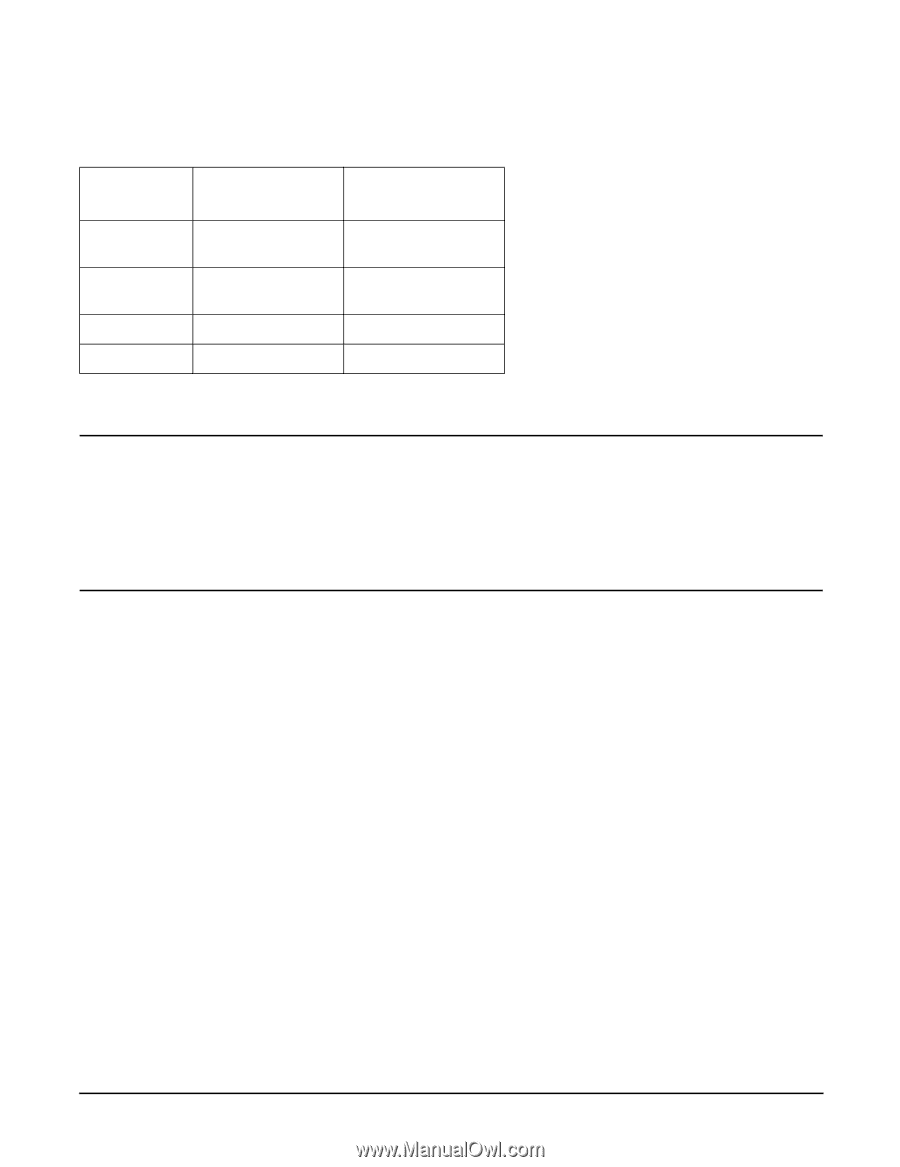
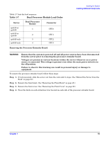
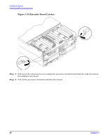
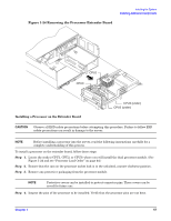
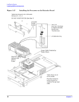
Table 1-7 lists the load sequence. Table 1-7 Dual Processor Module Load Order Server rp4410 or rp4440 rp4410 or rp4440 rp4440 only rp4440 only Dual Processor Module 1 2 3 4 Connector CPU0 CPU1 CPU2 CPU3 Removing the Processor Extender Board Installing the System Installing Additional Components WARNING Ensure that the system is powered off and all power sources have been disconnected from the server prior to removing the processor extender board. Voltages are present at various locations within the server whenever an ac power source is connected. This voltage is present even when the main power switch is in the off position. Failure to observe this warning can result in personal injury or damage to equipment. To remove the processor extender board, follow these steps: Step 1. If rack-mounted, slide the server out from the rack until it stops. (See "Extend the Server from the Rack" on page 22.) Step 2. Remove the front bezel. (See "Removing the Front Bezel" on page 28.) Step 3. Remove the front cover. (See "Removing the Front Cover" on page 29.) Step 4. Press the latch on each extraction lever located on each side of the processor extender board. Chapter 1 45
-
 1
1 -
2
-
3
-
4
-
5
-
6
-
7
-
8
-
9
-
10
-
11
-
12
-
13
-
14
-
15
-
16
-
17
-
18
-
19
-
20
-
21
-
22
-
23
-
24
-
25
-
26
-
27
-
28
-
29
-
30
-
31
-
32
-
33
-
34
-
35
-
36
-
37
-
38
-
39
-
 40
40 -
 41
41 -
 42
42 -
 43
43 -
 44
44 -
 45
45 -
 46
46 -
 47
47 -
 48
48 -
 49
49 -
 50
50 -
51
-
52
-
53
-
54
-
55
-
56
-
57
-
58
-
59
-
60
-
61
-
62
-
63
-
64
-
65
-
66
-
67
-
68
-
69
-
70
-
71
-
72
-
73
-
74
-
75
-
76
-
77
-
78
-
79
-
80
-
81
-
82
-
83
-
84
-
85
-
86
-
87
-
88
-
89
-
90
-
91
-
92
-
93
-
94
-
95
-
96
-
97
-
98
-
99
-
100
-
101
-
102
-
103
 |
 |