HP 9000 rp4410-4 Installation Guide, Sixth Edition - HP 9000 rp4410/rp4440 - Page 35
Removing the I/O Baseboard Assembly, Step 1., CAUTION
 |
View all HP 9000 rp4410-4 manuals
Add to My Manuals
Save this manual to your list of manuals |
Page 35 highlights
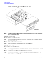
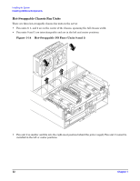
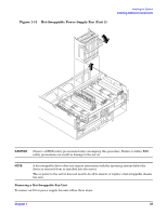
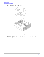
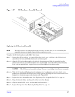
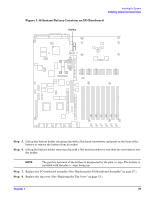
Removing the I/O Baseboard Assembly Installing the System Installing Additional Components CAUTION Before removing the I/O baseboard assembly, record all boot configuration settings displayed by the BCH INFO ALL command. These values might need to be reset after replacing the I/O baseboard assembly. To remove the I/O baseboard assembly, follow these steps: Step 1. If rack-mounted, slide the server out from the rack until it stops. (See "Extend the Server from the Rack" on page 22.) Step 2. Remove the top cover. (See "Removing the Top Cover" on page 30.) Step 3. Remove the three chassis fan units. (See "Removing a Hot-Swappable Fan Unit" on page 33.) Step 4. Unplug all external cabling attached to the ports at the rear of the I/O chassis. Step 5. Unplug the internal SCSI cables attached to the top of the host bus adapter (HBA) board in PCI slot 1. Step 6. Lift up on the locking lever attached to the side of the power supply cage to unplug the I/O baseboard assembly from the socket on the midplane riser board. Chapter 1 35
-
 1
1 -
2
-
3
-
4
-
5
-
6
-
7
-
8
-
9
-
10
-
11
-
12
-
13
-
14
-
15
-
16
-
17
-
18
-
19
-
20
-
21
-
22
-
23
-
24
-
25
-
26
-
27
-
28
-
29
-
 30
30 -
 31
31 -
 32
32 -
 33
33 -
 34
34 -
 35
35 -
 36
36 -
 37
37 -
 38
38 -
 39
39 -
 40
40 -
41
-
42
-
43
-
44
-
45
-
46
-
47
-
48
-
49
-
50
-
51
-
52
-
53
-
54
-
55
-
56
-
57
-
58
-
59
-
60
-
61
-
62
-
63
-
64
-
65
-
66
-
67
-
68
-
69
-
70
-
71
-
72
-
73
-
74
-
75
-
76
-
77
-
78
-
79
-
80
-
81
-
82
-
83
-
84
-
85
-
86
-
87
-
88
-
89
-
90
-
91
-
92
-
93
-
94
-
95
-
96
-
97
-
98
-
99
-
100
-
101
-
102
-
103
 |
 |