HP 9000 rp4410-4 Installation Guide, Sixth Edition - HP 9000 rp4410/rp4440 - Page 47
Removing the Processor Extender Board, Installing a Processor on the Extender Board
 |
View all HP 9000 rp4410-4 manuals
Add to My Manuals
Save this manual to your list of manuals |
Page 47 highlights
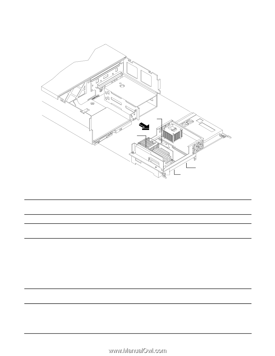
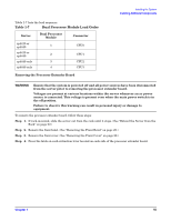
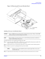
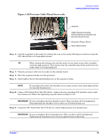
Installing the System Installing Additional Components Figure 1-24 Removing the Processor Extender Board CPU1 CPU0 Installing a Processor on the Extender Board CPU3 (under) CPU2 (under) CAUTION Observe all ESD safety precautions before attempting this procedure. Failure to follow ESD safety precautions can result in damage to the server. NOTE Before installing a processor into the server, read the following instructions carefully for a complete understanding of this process. To install a processor on the extender board, follow these steps: Step 1. Locate the socket (CPU1, CPU2, or CPU3) where you will install the dual processor module. (See Figure 1-24 and see "Processor Load Order" on page 44.) Step 2. Ensure that the cam on the processor socket lock is in the unlocked, counter-clockwise position. Step 3. Remove any protective packaging from the processor module. NOTE Protective covers can be installed to protect connector pins. These covers can be saved for future use. Step 4. Inspect the pins of the processor to be installed. Verify that the processor pins are not bent. Chapter 1 47
-
 1
1 -
2
-
3
-
4
-
5
-
6
-
7
-
8
-
9
-
10
-
11
-
12
-
13
-
14
-
15
-
16
-
17
-
18
-
19
-
20
-
21
-
22
-
23
-
24
-
25
-
26
-
27
-
28
-
29
-
30
-
31
-
32
-
33
-
34
-
35
-
36
-
37
-
38
-
39
-
40
-
41
-
 42
42 -
 43
43 -
 44
44 -
 45
45 -
 46
46 -
 47
47 -
 48
48 -
 49
49 -
 50
50 -
 51
51 -
 52
52 -
53
-
54
-
55
-
56
-
57
-
58
-
59
-
60
-
61
-
62
-
63
-
64
-
65
-
66
-
67
-
68
-
69
-
70
-
71
-
72
-
73
-
74
-
75
-
76
-
77
-
78
-
79
-
80
-
81
-
82
-
83
-
84
-
85
-
86
-
87
-
88
-
89
-
90
-
91
-
92
-
93
-
94
-
95
-
96
-
97
-
98
-
99
-
100
-
101
-
102
-
103
 |
 |