HP 9000 rp4410-4 Installation Guide, Sixth Edition - HP 9000 rp4410/rp4440 - Page 32
Hot-Swappable Chassis Fan Units, Hot-Swappable I/O Fans Units 0 and 1
 |
View all HP 9000 rp4410-4 manuals
Add to My Manuals
Save this manual to your list of manuals |
Page 32 highlights
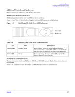
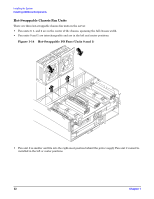
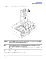
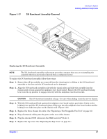
Installing the System Installing Additional Components Hot-Swappable Chassis Fan Units There are three hot-swappable chassis fan units in the server. • Fan units 0, 1, and 2 are in the center of the chassis, spanning the full chassis width. • Fan units 0 and 1 are interchangeable and are in the left and center positions. Figure 1-14 Hot-Swappable I/O Fans (Units 0 and 1) • Fan unit 2 is smaller and fits into the right-most position behind the power supply. Fan unit 2 cannot be installed in the left or center positions. 32 Chapter 1
-
 1
1 -
2
-
3
-
4
-
5
-
6
-
7
-
8
-
9
-
10
-
11
-
12
-
13
-
14
-
15
-
16
-
17
-
18
-
19
-
20
-
21
-
22
-
23
-
24
-
25
-
26
-
 27
27 -
 28
28 -
 29
29 -
 30
30 -
 31
31 -
 32
32 -
 33
33 -
 34
34 -
 35
35 -
 36
36 -
 37
37 -
38
-
39
-
40
-
41
-
42
-
43
-
44
-
45
-
46
-
47
-
48
-
49
-
50
-
51
-
52
-
53
-
54
-
55
-
56
-
57
-
58
-
59
-
60
-
61
-
62
-
63
-
64
-
65
-
66
-
67
-
68
-
69
-
70
-
71
-
72
-
73
-
74
-
75
-
76
-
77
-
78
-
79
-
80
-
81
-
82
-
83
-
84
-
85
-
86
-
87
-
88
-
89
-
90
-
91
-
92
-
93
-
94
-
95
-
96
-
97
-
98
-
99
-
100
-
101
-
102
-
103
 |
 |
Installing the System
Installing Additional Components
Chapter 1
32
Hot-Swappable Chassis Fan Units
There are three hot-swappable chassis fan units in the server.
•
Fan units 0, 1, and 2 are in the center of the chassis, spanning the full chassis width.
•
Fan units 0 and 1 are interchangeable and are in the left and center positions.
Figure 1-14
Hot-Swappable I/O Fans (Units 0 and 1)
•
Fan unit 2 is smaller and fits into the right-most position behind the power supply. Fan unit 2 cannot be
installed in the left or center positions.