HP 9000 rp4410-4 Installation Guide, Sixth Edition - HP 9000 rp4410/rp4440 - Page 46
Extender Board Latches, Step 5.
 |
View all HP 9000 rp4410-4 manuals
Add to My Manuals
Save this manual to your list of manuals |
Page 46 highlights
Installing the System Installing Additional Components Figure 1-23 Extender Board Latches Step 5. Pull out on the extraction levers to unplug the processor extender board from the socket located on the midplane riser board. Step 6. Pull out the processor extender board from the chassis. 46 Chapter 1
-
 1
1 -
2
-
3
-
4
-
5
-
6
-
7
-
8
-
9
-
10
-
11
-
12
-
13
-
14
-
15
-
16
-
17
-
18
-
19
-
20
-
21
-
22
-
23
-
24
-
25
-
26
-
27
-
28
-
29
-
30
-
31
-
32
-
33
-
34
-
35
-
36
-
37
-
38
-
39
-
40
-
 41
41 -
 42
42 -
 43
43 -
 44
44 -
 45
45 -
 46
46 -
 47
47 -
 48
48 -
 49
49 -
 50
50 -
 51
51 -
52
-
53
-
54
-
55
-
56
-
57
-
58
-
59
-
60
-
61
-
62
-
63
-
64
-
65
-
66
-
67
-
68
-
69
-
70
-
71
-
72
-
73
-
74
-
75
-
76
-
77
-
78
-
79
-
80
-
81
-
82
-
83
-
84
-
85
-
86
-
87
-
88
-
89
-
90
-
91
-
92
-
93
-
94
-
95
-
96
-
97
-
98
-
99
-
100
-
101
-
102
-
103
 |
 |
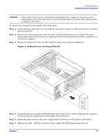
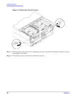
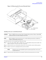
Installing the System
Installing Additional Components
Chapter 1
46
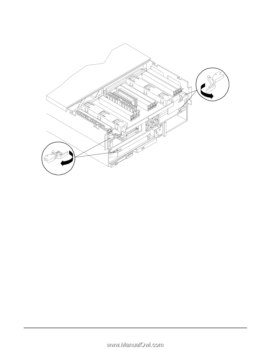
Figure 1-23 Extender Board Latches
Step 5.
Pull out on the extraction levers to unplug the processor extender board from the socket located on
the midplane riser board.
Step 6.
Pull out the processor extender board from the chassis.