HP 9000 rp4410-4 Installation Guide, Sixth Edition - HP 9000 rp4410/rp4440 - Page 44
Processor Load Order, Dual Processor Modules
 |
View all HP 9000 rp4410-4 manuals
Add to My Manuals
Save this manual to your list of manuals |
Page 44 highlights
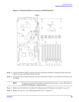
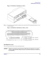
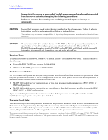
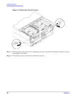
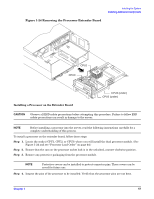
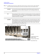
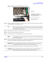
Installing the System Installing Additional Components Ensure that the system is powered off and all power sources have been disconnected from the server prior to attempting the following procedures. Failure to observe this warning can result in personal injury or damage to equipment. CAUTION Ensure that processor speed and cache size are identical for all processors. Failure to observe this caution results in performance degradation or system failure. The easiest way to ensure compatibility is by using dual processor modules with identical part numbers. CAUTION The processor extender board can be used in PA-RISC or Itanium processor based systems. A dipswitch is provided to configure processor extender board circuits. Ensure that the PA-RISC/Itanium dipswitch is set to PA-RISC for the HP 9000 rp4410 and rp4440 servers. If this switch is incorrectly set, the system does not enter into self test. Required Tools To install processors in the server, use the CPU Install Kit (HP part number 5069-5441). This kit consists of the following: • Disposable ESD Kit (HP part number A3024-80004) • CPU Install Tool (HP part number A7231-04046) Dual Processor Modules HP 9000 rp4410 and rp4440 servers use dual processor modules. Each module contains two processors. When only one processor is activated (a 1P/1C configuration of the HP 9000 rp4410 server), the second processor is installed but not enabled and is available for future use. • The HP 9000 rp4410 server can contain one or two dual processor modules to provide 1P/1C, 1P/2C, or 2P/2C configurations. • The HP 9000 rp4440 server can contain one, two, three, or four dual processor modules to provide 1P/2C, 2P/2C, 3P/2C, or 4P/2C configurations. If you are installing fewer than the maximum number of dual processor modules, the modules must be installed in the appropriate connectors. See Table 1-7. Processor Load Order You can install up to four dual processor modules on the processor extender board, which is located under the front cover in the top service bay, directly under the memory extender board. If you are installing fewer than the maximum number of dual processor modules (one in the rp4410 server or fewer than four in the rp4440 server), they must be installed in the designated locations on the processor extender board. The connectors (slots or sockets) on the processor extender board are labeled CPU0 through CPU3. CPU0 and CPU1 connectors are located on the top of the processor extender board, and CPU2 and CPU3 connectors are located on the bottom. 44 Chapter 1
-
 1
1 -
2
-
3
-
4
-
5
-
6
-
7
-
8
-
9
-
10
-
11
-
12
-
13
-
14
-
15
-
16
-
17
-
18
-
19
-
20
-
21
-
22
-
23
-
24
-
25
-
26
-
27
-
28
-
29
-
30
-
31
-
32
-
33
-
34
-
35
-
36
-
37
-
38
-
 39
39 -
 40
40 -
 41
41 -
 42
42 -
 43
43 -
 44
44 -
 45
45 -
 46
46 -
 47
47 -
 48
48 -
 49
49 -
50
-
51
-
52
-
53
-
54
-
55
-
56
-
57
-
58
-
59
-
60
-
61
-
62
-
63
-
64
-
65
-
66
-
67
-
68
-
69
-
70
-
71
-
72
-
73
-
74
-
75
-
76
-
77
-
78
-
79
-
80
-
81
-
82
-
83
-
84
-
85
-
86
-
87
-
88
-
89
-
90
-
91
-
92
-
93
-
94
-
95
-
96
-
97
-
98
-
99
-
100
-
101
-
102
-
103
 |
 |