HP Armada 4200 Armada 4100 and 4200 Families of Personal Computers Maintenance - Page 123
CPU Cover and Keyboard Assembly, Undock the computer from the auxiliary base
 |
View all HP Armada 4200 manuals
Add to My Manuals
Save this manual to your list of manuals |
Page 123 highlights
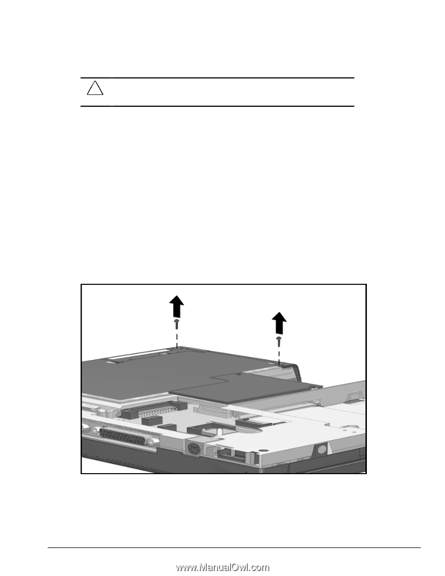
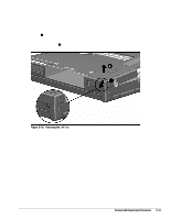
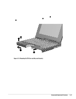
CAUTION: Installing the processor board without completing the recommended disassembly can flex the system board. This could cause an incomplete connection or damage to the system board. After the CPU cover has been removed (Section 5.5.6), place the processor board in position and squeeze it into place. Complete the assembly process by reversing the steps described in Section 5.5.6. 5.5.6 CPU Cover and Keyboard Assembly To remove the CPU cover and keyboard assembly, complete the following steps: 1. Disconnect the AC power and any external devices (Section 5.3.1). 2. Undock the computer from the auxiliary base, if necessary (Section 5.3.2). 3. Remove all battery packs (Section 5.3.3). 4. Remove the pointing device (Section 5.3.5). 5. Remove the hard drive (Section 5.3.6). 6. Remove two screws from the bottom left side of the CPU. Figure 5-32 Removing the Screws from the Bottom of the CPU Removal and Replacement Procedures 5-35
-
 1
1 -
2
-
3
-
4
-
5
-
6
-
7
-
8
-
9
-
10
-
11
-
12
-
13
-
14
-
15
-
16
-
17
-
18
-
19
-
20
-
21
-
22
-
23
-
24
-
25
-
26
-
27
-
28
-
29
-
30
-
31
-
32
-
33
-
34
-
35
-
36
-
37
-
38
-
39
-
40
-
41
-
42
-
43
-
44
-
45
-
46
-
47
-
48
-
49
-
50
-
51
-
52
-
53
-
54
-
55
-
56
-
57
-
58
-
59
-
60
-
61
-
62
-
63
-
64
-
65
-
66
-
67
-
68
-
69
-
70
-
71
-
72
-
73
-
74
-
75
-
76
-
77
-
78
-
79
-
80
-
81
-
82
-
83
-
84
-
85
-
86
-
87
-
88
-
89
-
90
-
91
-
92
-
93
-
94
-
95
-
96
-
97
-
98
-
99
-
100
-
101
-
102
-
103
-
104
-
105
-
106
-
107
-
108
-
109
-
110
-
111
-
112
-
113
-
114
-
115
-
116
-
117
-
 118
118 -
 119
119 -
 120
120 -
 121
121 -
 122
122 -
 123
123 -
 124
124 -
 125
125 -
 126
126 -
 127
127 -
 128
128 -
129
-
130
-
131
-
132
-
133
-
134
-
135
-
136
-
137
-
138
-
139
-
140
-
141
-
142
-
143
-
144
-
145
-
146
-
147
-
148
-
149
-
150
-
151
-
152
-
153
-
154
-
155
-
156
-
157
-
158
-
159
-
160
-
161
-
162
-
163
-
164
-
165
-
166
-
167
-
168
-
169
-
170
-
171
-
172
-
173
-
174
-
175
-
176
-
177
-
178
-
179
-
180
-
181
-
182
-
183
-
184
-
185
-
186
-
187
-
188
-
189
-
190
 |
 |