HP Armada 4200 Armada 4100 and 4200 Families of Personal Computers Maintenance - Page 139
Ensuring ESD Protection, Heatsink and Video Chip Heatpipe, To remove the heatsink
 |
View all HP Armada 4200 manuals
Add to My Manuals
Save this manual to your list of manuals |
Page 139 highlights
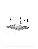
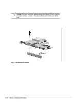
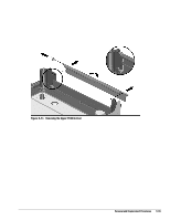
5.8.2 Ensuring ESD Protection When reinstalling the system board, it is important to include the grounding clip to maximize the ESD (electrostatic discharge) protection of the computer The grounding clip is located on the system board and is placed underneath the left rubber speaker isolation strip. Use the following precautions to ensure the grounding clip is in place when reinstalling the system board: s The grounding clip is installed in computers that have serial numbers higher than 650XXXXXXX. When the system board is removed, the grounding clip is removed with it. Be sure to replace the grounding clip when reinstalling the system board. s If you need to reinstall the clip, reinstall it by slipping the clip under the rubber speaker isolation strip. Be sure the fingers of the grounding clip make contact with the magnesium frame and left speaker frame. While replacing screws in the system board during reinstallation, secure the clip in place with screw number 2 as shown in Figure 5-55. s Include or replace the grounding clip whenever any service activity involves the removal and replacement of the system board. Failure to do so compromises the ESD protection of the computer. 5.8.3 Heatsink and Video Chip Heatpipe To remove the heatsink, complete the following procedures: 1. Disconnect the AC power and any external devices (Section 5.3.1). 2. Undock the computer from the auxiliary base, if necessary (Section 5.3.2). 3. Remove all battery packs (Section 5.4.3). 4. Remove the pointing device (Section 5.3.5). 5. Remove the hard drive. (Section 5.3.6). 6. Remove the memory cover (Section 5.5.1). 7. Remove the CPU base cover (Section 5.5.4). 8. Remove the processor shield and the processor (Section 5.5.5). 9. Remove the CPU cover/keyboard assembly (Section 5.5.6). 10. Remove the display assembly (Section 5.6). 11. Remove the clutch cover (Section 5.7.1). 12. Remove the clutch cover (Section 5.7.1). Removal and Replacement Procedures 5-51
-
 1
1 -
2
-
3
-
4
-
5
-
6
-
7
-
8
-
9
-
10
-
11
-
12
-
13
-
14
-
15
-
16
-
17
-
18
-
19
-
20
-
21
-
22
-
23
-
24
-
25
-
26
-
27
-
28
-
29
-
30
-
31
-
32
-
33
-
34
-
35
-
36
-
37
-
38
-
39
-
40
-
41
-
42
-
43
-
44
-
45
-
46
-
47
-
48
-
49
-
50
-
51
-
52
-
53
-
54
-
55
-
56
-
57
-
58
-
59
-
60
-
61
-
62
-
63
-
64
-
65
-
66
-
67
-
68
-
69
-
70
-
71
-
72
-
73
-
74
-
75
-
76
-
77
-
78
-
79
-
80
-
81
-
82
-
83
-
84
-
85
-
86
-
87
-
88
-
89
-
90
-
91
-
92
-
93
-
94
-
95
-
96
-
97
-
98
-
99
-
100
-
101
-
102
-
103
-
104
-
105
-
106
-
107
-
108
-
109
-
110
-
111
-
112
-
113
-
114
-
115
-
116
-
117
-
118
-
119
-
120
-
121
-
122
-
123
-
124
-
125
-
126
-
127
-
128
-
129
-
130
-
131
-
132
-
133
-
 134
134 -
 135
135 -
 136
136 -
 137
137 -
 138
138 -
 139
139 -
 140
140 -
 141
141 -
 142
142 -
 143
143 -
 144
144 -
145
-
146
-
147
-
148
-
149
-
150
-
151
-
152
-
153
-
154
-
155
-
156
-
157
-
158
-
159
-
160
-
161
-
162
-
163
-
164
-
165
-
166
-
167
-
168
-
169
-
170
-
171
-
172
-
173
-
174
-
175
-
176
-
177
-
178
-
179
-
180
-
181
-
182
-
183
-
184
-
185
-
186
-
187
-
188
-
189
-
190
 |
 |