HP Armada 4200 Armada 4100 and 4200 Families of Personal Computers Maintenance - Page 141
Press firmly on the foam-rubber spacer for 10 seconds to set the adhesive., the frame.
 |
View all HP Armada 4200 manuals
Add to My Manuals
Save this manual to your list of manuals |
Page 141 highlights
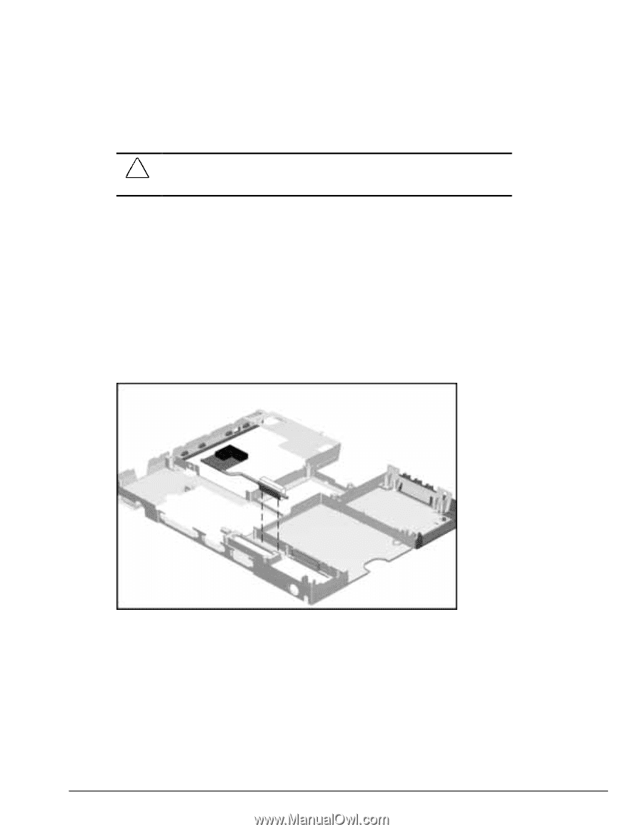
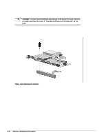
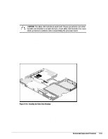
To install the video chip heatpipe: CAUTION: The video chip heatpipe is easily bent. Please use extreme care when handling and installing to prevent damage. A bent video chip heatpipe may cause stack-up tolerance problems when reassembling the processor board. 1. Complete steps 1-12 in section 5.8.2. 2. Removing the release liner protecting the thermal-adhesive strip on the small fin of the video chip heatpipe. 3. Place the video chip heatpipe into the frame as shown in the figure below locating the small fin between the cylindrical features with the thermal-adhesive and against the frame. 4. Press firmly on the foam-rubber spacer for 10 seconds to set the adhesive. 5. Reverse the disassembly procedures to reassemble the computer. Figure 5-50 Installing the Video Chip Heatpipe To remove the video chip heatpipe: 1. Complete steps 1-12 in section 5.8.2. 2. The video chip heatpipe is held in place with a double-sided thermal-adhesive strip. Lift the video chip heatpipe upward to loosen the adhesive bond. Use care to not bend the video chip heatpipe during removal. Removal and Replacement Procedures 5-53
-
 1
1 -
2
-
3
-
4
-
5
-
6
-
7
-
8
-
9
-
10
-
11
-
12
-
13
-
14
-
15
-
16
-
17
-
18
-
19
-
20
-
21
-
22
-
23
-
24
-
25
-
26
-
27
-
28
-
29
-
30
-
31
-
32
-
33
-
34
-
35
-
36
-
37
-
38
-
39
-
40
-
41
-
42
-
43
-
44
-
45
-
46
-
47
-
48
-
49
-
50
-
51
-
52
-
53
-
54
-
55
-
56
-
57
-
58
-
59
-
60
-
61
-
62
-
63
-
64
-
65
-
66
-
67
-
68
-
69
-
70
-
71
-
72
-
73
-
74
-
75
-
76
-
77
-
78
-
79
-
80
-
81
-
82
-
83
-
84
-
85
-
86
-
87
-
88
-
89
-
90
-
91
-
92
-
93
-
94
-
95
-
96
-
97
-
98
-
99
-
100
-
101
-
102
-
103
-
104
-
105
-
106
-
107
-
108
-
109
-
110
-
111
-
112
-
113
-
114
-
115
-
116
-
117
-
118
-
119
-
120
-
121
-
122
-
123
-
124
-
125
-
126
-
127
-
128
-
129
-
130
-
131
-
132
-
133
-
134
-
135
-
 136
136 -
 137
137 -
 138
138 -
 139
139 -
 140
140 -
 141
141 -
 142
142 -
 143
143 -
 144
144 -
 145
145 -
 146
146 -
147
-
148
-
149
-
150
-
151
-
152
-
153
-
154
-
155
-
156
-
157
-
158
-
159
-
160
-
161
-
162
-
163
-
164
-
165
-
166
-
167
-
168
-
169
-
170
-
171
-
172
-
173
-
174
-
175
-
176
-
177
-
178
-
179
-
180
-
181
-
182
-
183
-
184
-
185
-
186
-
187
-
188
-
189
-
190
 |
 |