HP Armada 4200 Armada 4100 and 4200 Families of Personal Computers Maintenance - Page 148
DualBay Eject Assembly, Remove the CPU cover/keyboard assembly
 |
View all HP Armada 4200 manuals
Add to My Manuals
Save this manual to your list of manuals |
Page 148 highlights
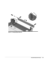
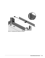
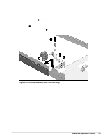
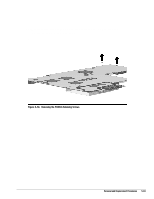
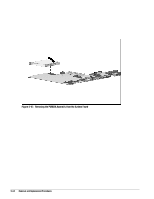
5.9.3 DualBay Eject Assembly To remove the DualBay eject assembly components, complete the following procedures: 1. Disconnect the AC power and any external devices (Section 5.3.1). 2. Undock the computer from the auxiliary base, if necessary (Section 5.3.2). 3. Remove all the battery packs (Section 5.4.3). 4. Remove the pointing device (Section 5.3.5). 5. Remove the hard drive. (Section 5.3.6). 6. Remove the CPU base cover (Section 5.5.4). 7. Remove the processor shield and the processor (Section 5.5.5). 8. Remove the CPU cover/keyboard assembly (Section 5.5.6). 9. Remove the display assembly (Section 5.6). 10. Remove the clutch cover (Section 5.7.1). 11. Remove the clutches (Section 5.7.2) 12. Remove the system board (Section 5.8.1). 5-60 Removal and Replacement Procedures
-
 1
1 -
2
-
3
-
4
-
5
-
6
-
7
-
8
-
9
-
10
-
11
-
12
-
13
-
14
-
15
-
16
-
17
-
18
-
19
-
20
-
21
-
22
-
23
-
24
-
25
-
26
-
27
-
28
-
29
-
30
-
31
-
32
-
33
-
34
-
35
-
36
-
37
-
38
-
39
-
40
-
41
-
42
-
43
-
44
-
45
-
46
-
47
-
48
-
49
-
50
-
51
-
52
-
53
-
54
-
55
-
56
-
57
-
58
-
59
-
60
-
61
-
62
-
63
-
64
-
65
-
66
-
67
-
68
-
69
-
70
-
71
-
72
-
73
-
74
-
75
-
76
-
77
-
78
-
79
-
80
-
81
-
82
-
83
-
84
-
85
-
86
-
87
-
88
-
89
-
90
-
91
-
92
-
93
-
94
-
95
-
96
-
97
-
98
-
99
-
100
-
101
-
102
-
103
-
104
-
105
-
106
-
107
-
108
-
109
-
110
-
111
-
112
-
113
-
114
-
115
-
116
-
117
-
118
-
119
-
120
-
121
-
122
-
123
-
124
-
125
-
126
-
127
-
128
-
129
-
130
-
131
-
132
-
133
-
134
-
135
-
136
-
137
-
138
-
139
-
140
-
141
-
142
-
 143
143 -
 144
144 -
 145
145 -
 146
146 -
 147
147 -
 148
148 -
 149
149 -
 150
150 -
 151
151 -
 152
152 -
 153
153 -
154
-
155
-
156
-
157
-
158
-
159
-
160
-
161
-
162
-
163
-
164
-
165
-
166
-
167
-
168
-
169
-
170
-
171
-
172
-
173
-
174
-
175
-
176
-
177
-
178
-
179
-
180
-
181
-
182
-
183
-
184
-
185
-
186
-
187
-
188
-
189
-
190
 |
 |