HP Armada 4200 Armada 4100 and 4200 Families of Personal Computers Maintenance - Page 142
Frame Components, Upper PCMCIA Door
 |
View all HP Armada 4200 manuals
Add to My Manuals
Save this manual to your list of manuals |
Page 142 highlights
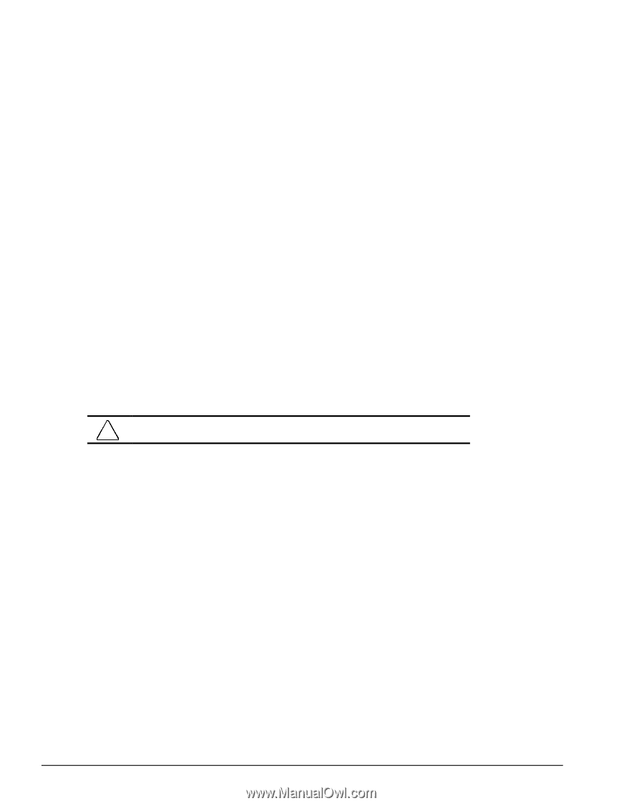
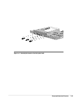
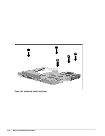
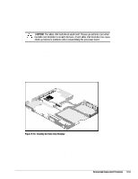
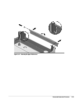
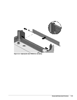
5.9 Frame Components Frame components include the upper and lower PCMCIA doors and the DualBay eject button components. Important: When installing the PCMCIA doors, the lower door must be installed first. 5.9.1 Upper PCMCIA Door To remove the upper PCMCIA door, complete the following procedures: 1. Disconnect the AC power and any external devices (Section 5.3.1). 2. Undock the computer from the auxiliary base, if necessary (Section 5.3.2). 3. Remove the handle battery pack (Section 5.3.3). 4. Remove the DualBay battery pack, if present (Section 5.3.4). 5. Remove the CPU cover/keyboard assembly (Section 5.5.6). 6. Grasp the upper door in the middle, slide it towards the front of the CPU, and flex it towards the inside of the computer. This allows the rear pin of the door to slide out of its slot while being compressed. CAUTION: The spring is very small and is easily lost. 5-54 Removal and Replacement Procedures
-
 1
1 -
2
-
3
-
4
-
5
-
6
-
7
-
8
-
9
-
10
-
11
-
12
-
13
-
14
-
15
-
16
-
17
-
18
-
19
-
20
-
21
-
22
-
23
-
24
-
25
-
26
-
27
-
28
-
29
-
30
-
31
-
32
-
33
-
34
-
35
-
36
-
37
-
38
-
39
-
40
-
41
-
42
-
43
-
44
-
45
-
46
-
47
-
48
-
49
-
50
-
51
-
52
-
53
-
54
-
55
-
56
-
57
-
58
-
59
-
60
-
61
-
62
-
63
-
64
-
65
-
66
-
67
-
68
-
69
-
70
-
71
-
72
-
73
-
74
-
75
-
76
-
77
-
78
-
79
-
80
-
81
-
82
-
83
-
84
-
85
-
86
-
87
-
88
-
89
-
90
-
91
-
92
-
93
-
94
-
95
-
96
-
97
-
98
-
99
-
100
-
101
-
102
-
103
-
104
-
105
-
106
-
107
-
108
-
109
-
110
-
111
-
112
-
113
-
114
-
115
-
116
-
117
-
118
-
119
-
120
-
121
-
122
-
123
-
124
-
125
-
126
-
127
-
128
-
129
-
130
-
131
-
132
-
133
-
134
-
135
-
136
-
 137
137 -
 138
138 -
 139
139 -
 140
140 -
 141
141 -
 142
142 -
 143
143 -
 144
144 -
 145
145 -
 146
146 -
 147
147 -
148
-
149
-
150
-
151
-
152
-
153
-
154
-
155
-
156
-
157
-
158
-
159
-
160
-
161
-
162
-
163
-
164
-
165
-
166
-
167
-
168
-
169
-
170
-
171
-
172
-
173
-
174
-
175
-
176
-
177
-
178
-
179
-
180
-
181
-
182
-
183
-
184
-
185
-
186
-
187
-
188
-
189
-
190
 |
 |