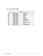
HP Armada 4200 Armada 4100 and 4200 Families of Personal Computers Maintenance - Page 181
Table A-7, Parallel, Table A-8, Serial
 |
View all HP Armada 4200 manuals
Add to My Manuals
Save this manual to your list of manuals |
Page 181 highlights
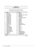
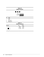
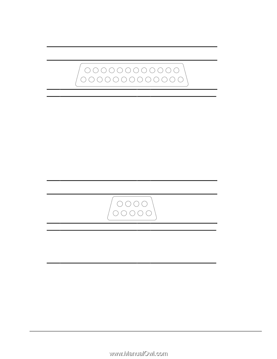
14 1 Pin Signal 1 Strobe 2 Data Bit 0 3 Data Bit 1 4 Data Bit 2 5 Data Bit 3 6 Data Bit 4 7 Data Bit 5 8 Data Bit 6 9 Data Bit 7 10 Acknowledge 11 Busy 12 Paper End 13 Select 6 1 Pin Signal 1 Carrier Detect 2 Receive Data 3 Transmit Data 4 Data Terminal Ready 5 Ground Table A-7 Parallel 25 13 Pin Signal 14 Auto Linefeed 15 Error 16 Initialize Printer 17 Select In 18 Ground 19 Ground 20 Ground 21 External Diskette Positive Drive Detect 22 External Diskette Negative Drive Detect 23 Ground 24 Ground 25 External Diskette Drive Switched to +5 V Table A-8 Serial 9 5 Pin Signal 6 Data Set Ready 7 Ready to Send 8 Clear to Send 9 Ring Indicator Connector Pin Assignments A-3
-
 1
1 -
2
-
3
-
4
-
5
-
6
-
7
-
8
-
9
-
10
-
11
-
12
-
13
-
14
-
15
-
16
-
17
-
18
-
19
-
20
-
21
-
22
-
23
-
24
-
25
-
26
-
27
-
28
-
29
-
30
-
31
-
32
-
33
-
34
-
35
-
36
-
37
-
38
-
39
-
40
-
41
-
42
-
43
-
44
-
45
-
46
-
47
-
48
-
49
-
50
-
51
-
52
-
53
-
54
-
55
-
56
-
57
-
58
-
59
-
60
-
61
-
62
-
63
-
64
-
65
-
66
-
67
-
68
-
69
-
70
-
71
-
72
-
73
-
74
-
75
-
76
-
77
-
78
-
79
-
80
-
81
-
82
-
83
-
84
-
85
-
86
-
87
-
88
-
89
-
90
-
91
-
92
-
93
-
94
-
95
-
96
-
97
-
98
-
99
-
100
-
101
-
102
-
103
-
104
-
105
-
106
-
107
-
108
-
109
-
110
-
111
-
112
-
113
-
114
-
115
-
116
-
117
-
118
-
119
-
120
-
121
-
122
-
123
-
124
-
125
-
126
-
127
-
128
-
129
-
130
-
131
-
132
-
133
-
134
-
135
-
136
-
137
-
138
-
139
-
140
-
141
-
142
-
143
-
144
-
145
-
146
-
147
-
148
-
149
-
150
-
151
-
152
-
153
-
154
-
155
-
156
-
157
-
158
-
159
-
160
-
161
-
162
-
163
-
164
-
165
-
166
-
167
-
168
-
169
-
170
-
171
-
172
-
173
-
174
-
175
-
 176
176 -
 177
177 -
 178
178 -
 179
179 -
 180
180 -
 181
181 -
 182
182 -
 183
183 -
 184
184 -
 185
185 -
 186
186 -
187
-
188
-
189
-
190
 |
 |
.
.
.
.
.
.
.
.
.
.
.
.
.
.
.
.
.
.
.
.
.
.
.
.
.
.
.
.
.
.
.
.
.
.
.
.
.
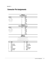
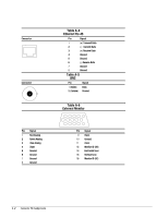
Connector Pin Assignments
A-3
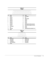
Table A-7
Parallel
1
14
25
13
Pin
Signal
Pin
Signal
1
Strobe
14
Auto Linefeed
2
Data Bit 0
15
Error
3
Data Bit 1
16
Initialize Printer
4
Data Bit 2
17
Select In
5
Data Bit 3
18
Ground
6
Data Bit 4
19
Ground
7
Data Bit 5
20
Ground
8
Data Bit 6
21
External Diskette Positive Drive Detect
9
Data Bit 7
22
External Diskette Negative Drive Detect
10
Acknowledge
23
Ground
11
Busy
24
Ground
12
Paper End
25
External Diskette Drive Switched to +5 V
13
Select
Table A-8
Serial
1
6
5
9
Pin
Signal
Pin
Signal
1
Carrier Detect
6
Data Set Ready
2
Receive Data
7
Ready to Send
3
Transmit Data
8
Clear to Send
4
Data Terminal Ready
9
Ring Indicator
5
Ground