HP EliteDesk 800 Maintenance and Service Guide - HP EliteDesk 800 G1 Tower, HP - Page 121
drive installed in the 3.5-inch optional drive bay. M3 isolation mounting guide screws for 2.5-inch
 |
View all HP EliteDesk 800 manuals
Add to My Manuals
Save this manual to your list of manuals |
Page 121 highlights
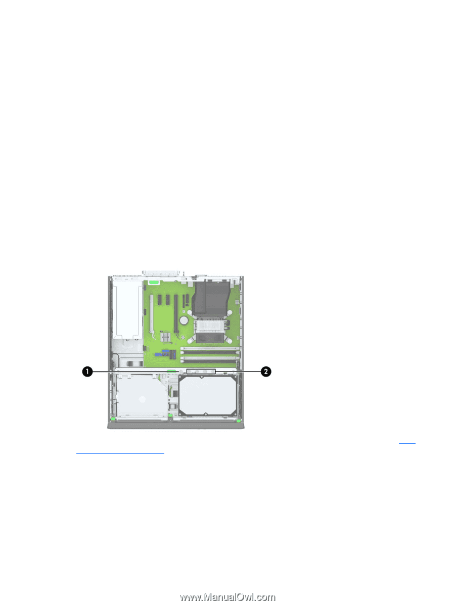
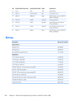
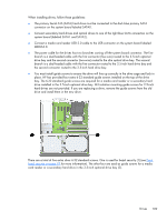
When installing drives, follow these guidelines: ● The primary Serial ATA (SATA) hard drive must be connected to the dark blue primary SATA connector on the system board labeled SATA0. ● Connect secondary hard drives and optical drives to one of the light blue SATA connectors on the system board (labeled SATA1 and SATA2). ● Connect a media card reader USB 3.0 cable to the USB connector on the system board labeled MEDIA3.0. ● The power cable for the drives has two branches coming off the system board connector. The first branch is a dual-headed cable with the first connector (four-wire) routed to the 3.5-inch optional drive bay and the second connector (two-wire) routed to the slim optical drive bay. The second branch is a dual-headed cable with the first connector routed to the 3.5-inch hard drive bay and the second connector routed to the 2.5-inch hard drive bay. ● You must install guide screws to ensure the drive will line up correctly in the drive cage and lock in place. HP has provided four extra 6-32 standard guide screws installed on the top of the drive bay. The 6-32 standard guide screws are required for a media card reader or a secondary hard drive installed in the 3.5-inch optional drive bay. M3 isolation mounting guide screws for 2.5-inch hard drives are not provided. If you are replacing a drive, remove the guide screws from the old drive and install them in the new drive. There are a total of five extra silver 6-32 standard screws. One is used for bezel security (1) (see Front bezel security on page 97 for more information). The other four are used as guide screws for a media card reader or a secondary hard drive in the 3.5-inch optional drive bay (2). Drives 109
-
 1
1 -
2
-
3
-
4
-
5
-
6
-
7
-
8
-
9
-
10
-
11
-
12
-
13
-
14
-
15
-
16
-
17
-
18
-
19
-
20
-
21
-
22
-
23
-
24
-
25
-
26
-
27
-
28
-
29
-
30
-
31
-
32
-
33
-
34
-
35
-
36
-
37
-
38
-
39
-
40
-
41
-
42
-
43
-
44
-
45
-
46
-
47
-
48
-
49
-
50
-
51
-
52
-
53
-
54
-
55
-
56
-
57
-
58
-
59
-
60
-
61
-
62
-
63
-
64
-
65
-
66
-
67
-
68
-
69
-
70
-
71
-
72
-
73
-
74
-
75
-
76
-
77
-
78
-
79
-
80
-
81
-
82
-
83
-
84
-
85
-
86
-
87
-
88
-
89
-
90
-
91
-
92
-
93
-
94
-
95
-
96
-
97
-
98
-
99
-
100
-
101
-
102
-
103
-
104
-
105
-
106
-
107
-
108
-
109
-
110
-
111
-
112
-
113
-
114
-
115
-
 116
116 -
 117
117 -
 118
118 -
 119
119 -
 120
120 -
 121
121 -
 122
122 -
 123
123 -
 124
124 -
 125
125 -
 126
126 -
127
-
128
-
129
-
130
-
131
-
132
-
133
-
134
-
135
-
136
-
137
-
138
-
139
-
140
-
141
-
142
-
143
-
144
-
145
-
146
-
147
-
148
-
149
-
150
-
151
-
152
-
153
-
154
-
155
-
156
-
157
-
158
-
159
-
160
-
161
-
162
-
163
-
164
-
165
-
166
-
167
-
168
-
169
-
170
-
171
-
172
-
173
-
174
-
175
-
176
-
177
-
178
-
179
-
180
-
181
-
182
-
183
-
184
-
185
-
186
-
187
-
188
-
189
-
190
-
191
-
192
-
193
-
194
-
195
-
196
-
197
-
198
-
199
-
200
-
201
-
202
-
203
-
204
-
205
-
206
-
207
-
208
-
209
-
210
-
211
-
212
-
213
-
214
-
215
-
216
-
217
-
218
-
219
-
220
-
221
-
222
-
223
-
224
-
225
-
226
-
227
-
228
-
229
-
230
-
231
-
232
-
233
-
234
-
235
-
236
-
237
-
238
-
239
-
240
-
241
-
242
-
243
-
244
-
245
-
246
-
247
-
248
-
249
-
250
-
251
-
252
-
253
-
254
-
255
-
256
-
257
-
258
-
259
-
260
-
261
-
262
-
263
-
264
-
265
-
266
-
267
-
268
-
269
-
270
-
271
-
272
-
273
-
274
-
275
-
276
-
277
-
278
-
279
-
280
-
281
-
282
-
283
-
284
-
285
-
286
-
287
-
288
-
289
-
290
-
291
-
292
-
293
-
294
-
295
-
296
 |
 |