HP EliteDesk 800 Maintenance and Service Guide - HP EliteDesk 800 G1 Tower, HP - Page 178
Card reader
 |
View all HP EliteDesk 800 manuals
Add to My Manuals
Save this manual to your list of manuals |
Page 178 highlights
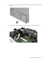
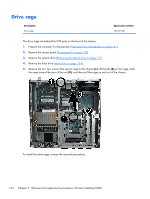
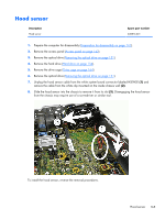
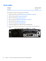
Card reader Description Card reader Spare part number xxxxxx-001 The card reader is secured to the front right corner of the chassis. 1. Prepare the computer for disassembly (Preparation for disassembly on page 141). 2. Remove the access panel (Access panel on page 142). 3. Remove the front bezel (Front bezel on page 143). 4. Remove the optical drive (Removing the optical drive on page 151). 5. Remove the hard drive (Hard drive on page 154). 6. Remove the drive cage (Drive cage on page 164). 7. Disconnect the cable from the system board connector labeled MEDIA. 8. On the outside of the chassis, remove the one Torx screw that secures the card reader to the chassis. 166 Chapter 7 Removal and replacement procedures: Ultra-slim Desktop (USDT)
-
 1
1 -
2
-
3
-
4
-
5
-
6
-
7
-
8
-
9
-
10
-
11
-
12
-
13
-
14
-
15
-
16
-
17
-
18
-
19
-
20
-
21
-
22
-
23
-
24
-
25
-
26
-
27
-
28
-
29
-
30
-
31
-
32
-
33
-
34
-
35
-
36
-
37
-
38
-
39
-
40
-
41
-
42
-
43
-
44
-
45
-
46
-
47
-
48
-
49
-
50
-
51
-
52
-
53
-
54
-
55
-
56
-
57
-
58
-
59
-
60
-
61
-
62
-
63
-
64
-
65
-
66
-
67
-
68
-
69
-
70
-
71
-
72
-
73
-
74
-
75
-
76
-
77
-
78
-
79
-
80
-
81
-
82
-
83
-
84
-
85
-
86
-
87
-
88
-
89
-
90
-
91
-
92
-
93
-
94
-
95
-
96
-
97
-
98
-
99
-
100
-
101
-
102
-
103
-
104
-
105
-
106
-
107
-
108
-
109
-
110
-
111
-
112
-
113
-
114
-
115
-
116
-
117
-
118
-
119
-
120
-
121
-
122
-
123
-
124
-
125
-
126
-
127
-
128
-
129
-
130
-
131
-
132
-
133
-
134
-
135
-
136
-
137
-
138
-
139
-
140
-
141
-
142
-
143
-
144
-
145
-
146
-
147
-
148
-
149
-
150
-
151
-
152
-
153
-
154
-
155
-
156
-
157
-
158
-
159
-
160
-
161
-
162
-
163
-
164
-
165
-
166
-
167
-
168
-
169
-
170
-
171
-
172
-
 173
173 -
 174
174 -
 175
175 -
 176
176 -
 177
177 -
 178
178 -
 179
179 -
 180
180 -
 181
181 -
 182
182 -
 183
183 -
184
-
185
-
186
-
187
-
188
-
189
-
190
-
191
-
192
-
193
-
194
-
195
-
196
-
197
-
198
-
199
-
200
-
201
-
202
-
203
-
204
-
205
-
206
-
207
-
208
-
209
-
210
-
211
-
212
-
213
-
214
-
215
-
216
-
217
-
218
-
219
-
220
-
221
-
222
-
223
-
224
-
225
-
226
-
227
-
228
-
229
-
230
-
231
-
232
-
233
-
234
-
235
-
236
-
237
-
238
-
239
-
240
-
241
-
242
-
243
-
244
-
245
-
246
-
247
-
248
-
249
-
250
-
251
-
252
-
253
-
254
-
255
-
256
-
257
-
258
-
259
-
260
-
261
-
262
-
263
-
264
-
265
-
266
-
267
-
268
-
269
-
270
-
271
-
272
-
273
-
274
-
275
-
276
-
277
-
278
-
279
-
280
-
281
-
282
-
283
-
284
-
285
-
286
-
287
-
288
-
289
-
290
-
291
-
292
-
293
-
294
-
295
-
296
 |
 |
Card reader
Description
Spare part number
Card reader
xxxxxx-001
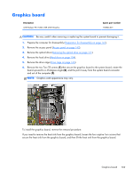
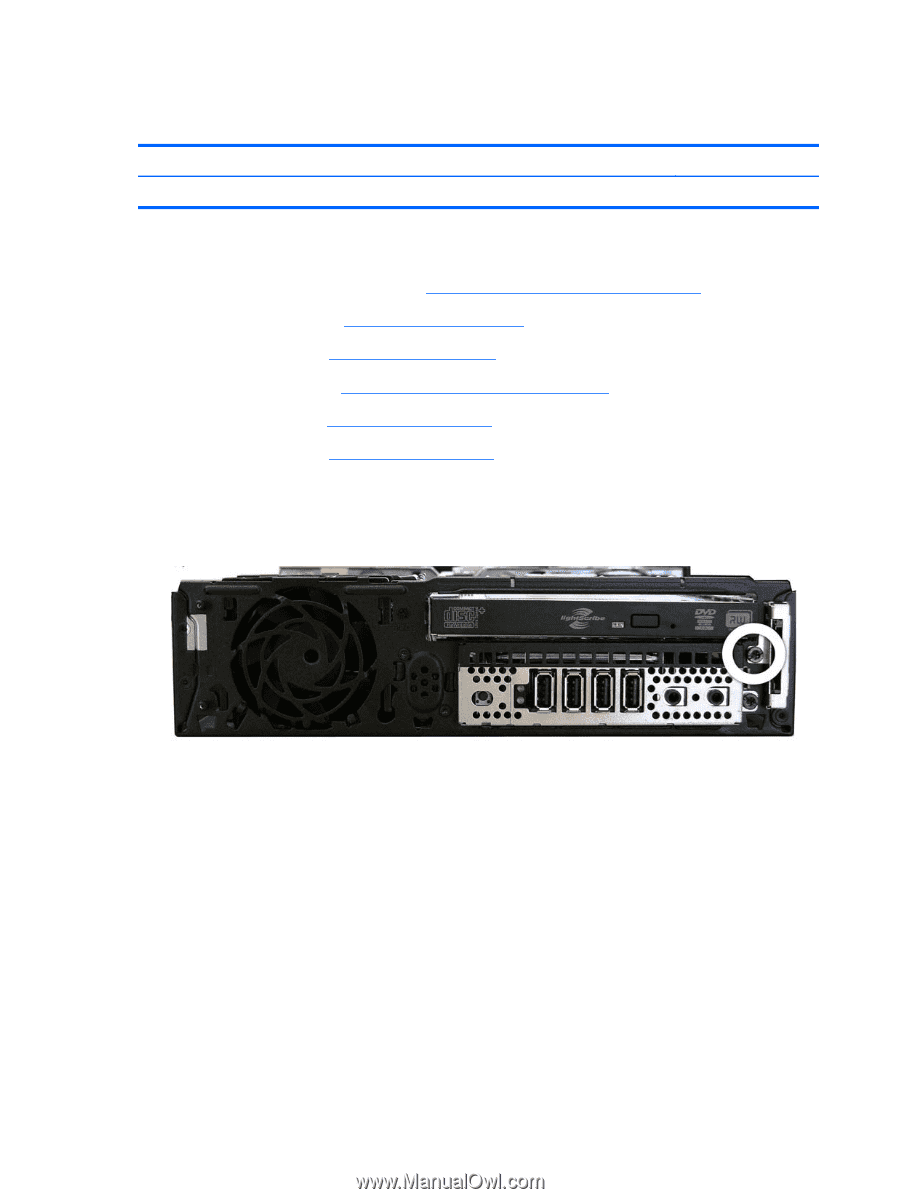
The card reader is secured to the front right corner of the chassis.
1.
Prepare the computer for disassembly (
Preparation for disassembly
on page
141
).
2.
Remove the access panel (
Access panel
on page
142
).
3.
Remove the front bezel (
Front bezel
on page
143
).
4.
Remove the optical drive (
Removing the optical drive
on page
151
).
5.
Remove the hard drive (
Hard drive
on page
154
).
6.
Remove the drive cage (
Drive cage
on page
164
).
7.
Disconnect the cable from the system board connector labeled MEDIA.
8.
On the outside of the chassis, remove the one Torx screw that secures the card reader to the
chassis.
166
Chapter 7
Removal and replacement procedures: Ultra-slim Desktop (USDT)