HP EliteDesk 800 Maintenance and Service Guide - HP EliteDesk 800 G1 Tower, HP - Page 158
Refer to the following illustration and table to identify the system board connectors., - mini
 |
View all HP EliteDesk 800 manuals
Add to My Manuals
Save this manual to your list of manuals |
Page 158 highlights
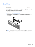
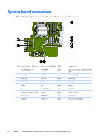
System board connections Refer to the following illustration and table to identify the system board connectors. No. System Board Connector System Board Label Color 1 Mini PCI Express x1 X1PCIEXP1 black 2 Mini-SATA mSATA 3 Hood Lock HLOCK 4 SATA 3.0 SATA1 5 Battery BAT 6 Power SATA PWR1 7 Mobile PCI Express Module MXM 8 Hood Sensor HSENSE 9 USB 3.0 MEDIA 3.0 white black light blue black white black white black Component Expansion Card (for example, WLAN card) Ultra-Small SSD Hood Lock Optical Drive Battery Optical Drive Graphics Card Hood Sensor SD Media Card Reader 146 Chapter 7 Removal and replacement procedures: Ultra-slim Desktop (USDT)
-
 1
1 -
2
-
3
-
4
-
5
-
6
-
7
-
8
-
9
-
10
-
11
-
12
-
13
-
14
-
15
-
16
-
17
-
18
-
19
-
20
-
21
-
22
-
23
-
24
-
25
-
26
-
27
-
28
-
29
-
30
-
31
-
32
-
33
-
34
-
35
-
36
-
37
-
38
-
39
-
40
-
41
-
42
-
43
-
44
-
45
-
46
-
47
-
48
-
49
-
50
-
51
-
52
-
53
-
54
-
55
-
56
-
57
-
58
-
59
-
60
-
61
-
62
-
63
-
64
-
65
-
66
-
67
-
68
-
69
-
70
-
71
-
72
-
73
-
74
-
75
-
76
-
77
-
78
-
79
-
80
-
81
-
82
-
83
-
84
-
85
-
86
-
87
-
88
-
89
-
90
-
91
-
92
-
93
-
94
-
95
-
96
-
97
-
98
-
99
-
100
-
101
-
102
-
103
-
104
-
105
-
106
-
107
-
108
-
109
-
110
-
111
-
112
-
113
-
114
-
115
-
116
-
117
-
118
-
119
-
120
-
121
-
122
-
123
-
124
-
125
-
126
-
127
-
128
-
129
-
130
-
131
-
132
-
133
-
134
-
135
-
136
-
137
-
138
-
139
-
140
-
141
-
142
-
143
-
144
-
145
-
146
-
147
-
148
-
149
-
150
-
151
-
152
-
 153
153 -
 154
154 -
 155
155 -
 156
156 -
 157
157 -
 158
158 -
 159
159 -
 160
160 -
 161
161 -
 162
162 -
 163
163 -
164
-
165
-
166
-
167
-
168
-
169
-
170
-
171
-
172
-
173
-
174
-
175
-
176
-
177
-
178
-
179
-
180
-
181
-
182
-
183
-
184
-
185
-
186
-
187
-
188
-
189
-
190
-
191
-
192
-
193
-
194
-
195
-
196
-
197
-
198
-
199
-
200
-
201
-
202
-
203
-
204
-
205
-
206
-
207
-
208
-
209
-
210
-
211
-
212
-
213
-
214
-
215
-
216
-
217
-
218
-
219
-
220
-
221
-
222
-
223
-
224
-
225
-
226
-
227
-
228
-
229
-
230
-
231
-
232
-
233
-
234
-
235
-
236
-
237
-
238
-
239
-
240
-
241
-
242
-
243
-
244
-
245
-
246
-
247
-
248
-
249
-
250
-
251
-
252
-
253
-
254
-
255
-
256
-
257
-
258
-
259
-
260
-
261
-
262
-
263
-
264
-
265
-
266
-
267
-
268
-
269
-
270
-
271
-
272
-
273
-
274
-
275
-
276
-
277
-
278
-
279
-
280
-
281
-
282
-
283
-
284
-
285
-
286
-
287
-
288
-
289
-
290
-
291
-
292
-
293
-
294
-
295
-
296
 |
 |
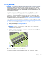
System board connections
Refer to the following illustration and table to identify the system board connectors.
No.
System Board Connector
System Board Label
Color
Component
1
Mini PCI Express x1
X1PCIEXP1
black
Expansion Card (for example, WLAN
card)
2
Mini-SATA
mSATA
white
Ultra-Small SSD
3
Hood Lock
HLOCK
black
Hood Lock
4
SATA 3.0
SATA1
light blue
Optical Drive
5
Battery
BAT
black
Battery
6
Power
SATA PWR1
white
Optical Drive
7
Mobile PCI Express Module
MXM
black
Graphics Card
8
Hood Sensor
HSENSE
white
Hood Sensor
9
USB 3.0
MEDIA 3.0
black
SD Media Card Reader
146
Chapter 7
Removal and replacement procedures: Ultra-slim Desktop (USDT)