HP LaserJet Managed MFP E82540-E82560 On-Site Installation Guide - Page 52
Underneath, there is a plastic handle located in the middle to assist in the installation into engine.
 |
View all HP LaserJet Managed MFP E82540-E82560 manuals
Add to My Manuals
Save this manual to your list of manuals |
Page 52 highlights
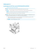
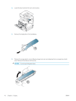
2. Remove red tape pull straight in direction of the arrow. Remove second shipping material from the developing unit by pulling the red tape down off the engine and then pull straight out of the developing unit. 1 2 3. Remove image drum from shipping bag. Remove orange shipping material from drum, release tabs on center (callout 2) and at each ends (callout 1,3) to release orange shipping material (callout 4). CAUTION: Do not touch the green drum and reduce its exposure to light. 4 3 4. Underneath, there is a plastic handle located in the middle to assist in the installation into engine. ▲ Install image drum in the upper opening in the engine. CAUTION: Verify the guide on top of the imaging drum is properly aligned to the guide inside the engine before pushing. If it is not, the drum will be scratched. 46 Chapter 5 Staging ENWW
-
 1
1 -
2
-
3
-
4
-
5
-
6
-
7
-
8
-
9
-
10
-
11
-
12
-
13
-
14
-
15
-
16
-
17
-
18
-
19
-
20
-
21
-
22
-
23
-
24
-
25
-
26
-
27
-
28
-
29
-
30
-
31
-
32
-
33
-
34
-
35
-
36
-
37
-
38
-
39
-
40
-
41
-
42
-
43
-
44
-
45
-
46
-
 47
47 -
 48
48 -
 49
49 -
 50
50 -
 51
51 -
 52
52 -
 53
53 -
 54
54 -
 55
55 -
 56
56 -
 57
57 -
58
-
59
-
60
-
61
-
62
-
63
-
64
-
65
-
66
-
67
-
68
-
69
-
70
-
71
-
72
-
73
-
74
-
75
-
76
-
77
-
78
-
79
-
80
-
81
-
82
-
83
-
84
-
85
-
86
-
87
-
88
-
89
-
90
-
91
-
92
-
93
-
94
-
95
-
96
-
97
-
98
-
99
-
100
-
101
-
102
-
103
-
104
-
105
-
106
 |
 |
