HP LaserJet Managed MFP E82540-E82560 On-Site Installation Guide - Page 85
Install the 3000-sheet sHCI, The engine assembly is heavy and requires four people to lift.
 |
View all HP LaserJet Managed MFP E82540-E82560 manuals
Add to My Manuals
Save this manual to your list of manuals |
Page 85 highlights
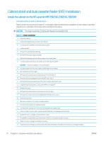
Install the 3000-sheet sHCI The HCI tray is configured for size A4 by default. Use the following steps to configure the HCI tray for LTR sizes. . Click here to view a video for this procedure. CAUTION: The engine assembly is heavy and requires four people to lift. Please review the LaserJet A3 videos for a complete understanding of the installation of each device. Use these checklists as a reminder of the steps demonstrated in the videos. Table 8-3 Cabinet installation ❑ Power down the MFP. ❑ Unpack the sHCI and attachment hardware. ❑ Pinch and remove the covers on the front and the rear guides. ❑ Locate the LTR positions at the top and on the bottom of each guide. NOTE: Push the tray down to see the bottom locations. ❑ Remove the screws and move the guides to the LTR position. ❑ Reinstall the screws and covers on the front and the rear guides. ❑ Remove the short "dummy" guides from the LTR positions. ❑ Remove the tall side guides from the A4 positions and install in the LTR position. ❑ Remove the short dummy guides in the A4 position and install in the LTR positions. ❑ Remove the covers and the screws on the right lower cover on the MFP input device. NOTE: The sHCI is not compatible with a stand. ❑ Open the lower right door slightly to allow the surrounding cover to be remove. ❑ Hang the two attachment brackets on the side of the MFP input device. ❑ Install two screws into each bracket. ❑ Locate the rail and rail support bracket. ❑ Find the tab on the rail support bracket and not how it engages on the bottom of the MFP input device. ❑ Position the rail into the support bracket. NOTE: The "U" shape of the rail faces the grounding clip on the support bracket. ❑ Extend the rail until it stops in the bracket. ❑ Position the support bracket under the device and engage the tab. ❑ Install four screws to secure the bracket to the MFP. ❑ Pry from the rear to remove knock out covers at the four locations on the lower right cover. ❑ Reinstall the lower right cover. ❑ Remove the paper path opening cover just above the lower right door. ❑ Install the paper path guide. Note the three tabs are located at the TOP of the opening. ❑ Fully extend the attachment rail and position the sHCI near the end of the rail. ENWW Install the 3000-sheet sHCI 79
-
 1
1 -
2
-
3
-
4
-
5
-
6
-
7
-
8
-
9
-
10
-
11
-
12
-
13
-
14
-
15
-
16
-
17
-
18
-
19
-
20
-
21
-
22
-
23
-
24
-
25
-
26
-
27
-
28
-
29
-
30
-
31
-
32
-
33
-
34
-
35
-
36
-
37
-
38
-
39
-
40
-
41
-
42
-
43
-
44
-
45
-
46
-
47
-
48
-
49
-
50
-
51
-
52
-
53
-
54
-
55
-
56
-
57
-
58
-
59
-
60
-
61
-
62
-
63
-
64
-
65
-
66
-
67
-
68
-
69
-
70
-
71
-
72
-
73
-
74
-
75
-
76
-
77
-
78
-
79
-
 80
80 -
 81
81 -
 82
82 -
 83
83 -
 84
84 -
 85
85 -
 86
86 -
 87
87 -
 88
88 -
 89
89 -
 90
90 -
91
-
92
-
93
-
94
-
95
-
96
-
97
-
98
-
99
-
100
-
101
-
102
-
103
-
104
-
105
-
106
 |
 |
