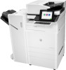
HP LaserJet Managed MFP E82540-E82560 On-Site Installation Guide - Page 82
-sheet HCI, Install the 2000-sheet HCI on the HP Color LaserJet MFP E87640, E87650, E87660
 |
View all HP LaserJet Managed MFP E82540-E82560 manuals
Add to My Manuals
Save this manual to your list of manuals |
Page 82 highlights
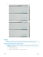
2000-sheet HCI Install the 2000-sheet HCI on the HP Color LaserJet MFP E87640, E87650, E87660 . Click here to view a video of this procedure. Please review the LaserJet A3 videos for a complete understanding of the installation of each device. Use these checklists as a reminder of the steps demonstrated in the videos. Table 8-2 2000-sheet HCI installation ❑ Unpack the 2000-sheet HCI (high capacity input). ❑ Remove the packing foam and tape. NOTE: The 2000-sheet HCI comes configured for A4 paper size, follow these steps to convert to letter LTR size. ❑ Locate the paper guides at the front and the rear that need to be moved. ❑ Remove one screw on top and remove the right rear guide. NOTE: The locating slots and tabs on the top and the tabs on the bottom of guide. NOTE: The A4/LTR slots in the bottom of the tray. ❑ Align the guide to the LTR locations at the top and on the bottom. ❑ Reinstall the screw to secure the guide. ❑ Perform the same steps for the front right guide. ❑ Remove one screw which secure the front left guide at the bottom.. NOTE: This is a plastic tapping screw. Be sure not to over-tighten when reinstalling. ❑ Remove the front left guide and not the tabs on the bottom and the corresponding LTR and A4 slots on the bottom of the tray. ❑ Align the guide to the LTR locations at the bottom. ❑ Reinstall the screw. TIP: When reinstalling, turn the screw CCW first and then CW to find the original threads. ❑ Remove one screw which secures the left rear guide at the bottom. ❑ Remove the guide and lay flat in the tray. ❑ Note the A4/LTR alignment bracket on the rear of the guide. ❑ Remove one screw and rotate the bracket to the LTR orientation. ❑ Replace the self-tapping screw. Be careful to start correctly and don't over-tighten. NOTE: If the guides need to be adjusted AFTER the MFP is installed, access to the rear guides requires that the 2000-sheet HCI tray rails be release to allow the tray to extend out further. ❑ Locate the thumbscrews which are used to attach the MFP to the 2000-sheet HCI. Set these aside for later. ❑ Unpack the MFP. ❑ Remove packing foam and tape. ❑ Remove the scanner support bracket. ❑ Remove the package containing the drum units and set aside. 76 Chapter 8 Complete installation procedures ENWW
-
 1
1 -
2
-
3
-
4
-
5
-
6
-
7
-
8
-
9
-
10
-
11
-
12
-
13
-
14
-
15
-
16
-
17
-
18
-
19
-
20
-
21
-
22
-
23
-
24
-
25
-
26
-
27
-
28
-
29
-
30
-
31
-
32
-
33
-
34
-
35
-
36
-
37
-
38
-
39
-
40
-
41
-
42
-
43
-
44
-
45
-
46
-
47
-
48
-
49
-
50
-
51
-
52
-
53
-
54
-
55
-
56
-
57
-
58
-
59
-
60
-
61
-
62
-
63
-
64
-
65
-
66
-
67
-
68
-
69
-
70
-
71
-
72
-
73
-
74
-
75
-
76
-
 77
77 -
 78
78 -
 79
79 -
 80
80 -
 81
81 -
 82
82 -
 83
83 -
 84
84 -
 85
85 -
 86
86 -
 87
87 -
88
-
89
-
90
-
91
-
92
-
93
-
94
-
95
-
96
-
97
-
98
-
99
-
100
-
101
-
102
-
103
-
104
-
105
-
106
 |
 |
