HP LaserJet P2050 Service Manual - Page 206
Heating element check, High-voltage contacts check, Checking the print cartridge contacts
 |
View all HP LaserJet P2050 manuals
Add to My Manuals
Save this manual to your list of manuals |
Page 206 highlights
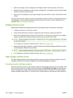
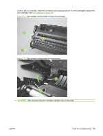
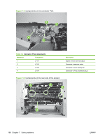
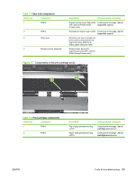
3. Mark the drive gear on the cartridge with a felt-tipped marker. Note the position of the mark. 4. Replace the print cartridge and close the print-cartridge door. The startup sequence should rotate the drum enough to move the mark. 5. Open the print-cartridge door and inspect the gear that was marked in step 3. Verify that the mark moved. If the mark did not move, inspect the main drive assembly to make sure that it is meshing with the print cartridge gears. If the drive gears appear functional and the drum does not move, replace the print cartridge. See Print cartridge on page 102. Heating element check Paper passes between the heating element and a soft pressure roller to fuse toner to the paper. 1. Unplug the product for at least ten minutes. 2. Verify that the thermistor connector is seated into both the product chassis and the ECU. 3. Remove the heating element connector from the ECU. To measure the continuity of the heating element, measure the resistance between the two pins at the end of the cable. NOTE: Normal resistance is 25 ohms +/- 10 ohms for the 110 V product and 80 ohms +/- 20 ohms for the 220 V product. If no resistance is measured, replace the fuser. See Fuser on page 158. 4. Remove the thermistor connector, and then measure the resistance between J206 pins one and two and between J206 pins three and four. NOTE: Normal resistance between both pairs of pins is 370K ohms +/- 50K ohms at 20° C (68° F). 5. If no resistance is measured, replace the fuser. See Fuser on page 158, High-voltage contacts check The high-voltage contacts in the product must have a good connection with the contacts on the print cartridge to provide the necessary voltages for the electrophotographic processes. Checking the print cartridge contacts When the product is turned on, high voltage is placed on the developer roller of the print cartridge. If the antenna does not detect this voltage, the product displays an Install Black Cartridge message. Remove the print cartridge and visually inspect the three connection points on the ends of the print cartridge: primary charging contact (callout 1), developer roller contact (callout 2), and antenna contact (callout 3). 194 Chapter 7 Solve problems ENWW
-
 1
1 -
2
-
3
-
4
-
5
-
6
-
7
-
8
-
9
-
10
-
11
-
12
-
13
-
14
-
15
-
16
-
17
-
18
-
19
-
20
-
21
-
22
-
23
-
24
-
25
-
26
-
27
-
28
-
29
-
30
-
31
-
32
-
33
-
34
-
35
-
36
-
37
-
38
-
39
-
40
-
41
-
42
-
43
-
44
-
45
-
46
-
47
-
48
-
49
-
50
-
51
-
52
-
53
-
54
-
55
-
56
-
57
-
58
-
59
-
60
-
61
-
62
-
63
-
64
-
65
-
66
-
67
-
68
-
69
-
70
-
71
-
72
-
73
-
74
-
75
-
76
-
77
-
78
-
79
-
80
-
81
-
82
-
83
-
84
-
85
-
86
-
87
-
88
-
89
-
90
-
91
-
92
-
93
-
94
-
95
-
96
-
97
-
98
-
99
-
100
-
101
-
102
-
103
-
104
-
105
-
106
-
107
-
108
-
109
-
110
-
111
-
112
-
113
-
114
-
115
-
116
-
117
-
118
-
119
-
120
-
121
-
122
-
123
-
124
-
125
-
126
-
127
-
128
-
129
-
130
-
131
-
132
-
133
-
134
-
135
-
136
-
137
-
138
-
139
-
140
-
141
-
142
-
143
-
144
-
145
-
146
-
147
-
148
-
149
-
150
-
151
-
152
-
153
-
154
-
155
-
156
-
157
-
158
-
159
-
160
-
161
-
162
-
163
-
164
-
165
-
166
-
167
-
168
-
169
-
170
-
171
-
172
-
173
-
174
-
175
-
176
-
177
-
178
-
179
-
180
-
181
-
182
-
183
-
184
-
185
-
186
-
187
-
188
-
189
-
190
-
191
-
192
-
193
-
194
-
195
-
196
-
197
-
198
-
199
-
200
-
 201
201 -
 202
202 -
 203
203 -
 204
204 -
 205
205 -
 206
206 -
 207
207 -
 208
208 -
 209
209 -
 210
210 -
 211
211 -
212
-
213
-
214
-
215
-
216
-
217
-
218
-
219
-
220
-
221
-
222
-
223
-
224
-
225
-
226
-
227
-
228
-
229
-
230
-
231
-
232
-
233
-
234
-
235
-
236
-
237
-
238
-
239
-
240
-
241
-
242
-
243
-
244
-
245
-
246
-
247
-
248
-
249
-
250
-
251
-
252
-
253
-
254
-
255
-
256
-
257
-
258
-
259
-
260
-
261
-
262
-
263
-
264
-
265
-
266
-
267
-
268
-
269
-
270
-
271
-
272
-
273
-
274
-
275
-
276
-
277
-
278
-
279
-
280
-
281
-
282
-
283
-
284
-
285
-
286
-
287
-
288
-
289
-
290
-
291
-
292
-
293
-
294
-
295
-
296
-
297
-
298
-
299
-
300
-
301
-
302
-
303
-
304
-
305
-
306
-
307
-
308
-
309
-
310
-
311
-
312
-
313
-
314
-
315
-
316
-
317
-
318
-
319
-
320
-
321
-
322
 |
 |