HP LaserJet P2050 Service Manual - Page 228
Alert message, Description, Recommended action, Door Open, Engine communication error
 |
View all HP LaserJet P2050 manuals
Add to My Manuals
Save this manual to your list of manuals |
Page 228 highlights
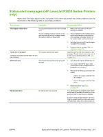
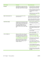
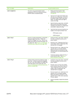
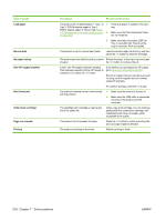
Alert message Door Open Engine communication error Install black cartridge Jam in cartridge area Description Recommended action Opening the front door opens the front door 1. switch (SW301) and disables the +24 V to the high-voltage contacts on the print cartridges. Remove the left cover, and then open and close the front door. Determine if SW301 closes when the door closes. 2. Make sure that the two connectors from the engine control PCA to the switch are securely installed on the switch contacts. 3. Replace the front door switch (SW301). if the message persists. See Cartridgedoor switch on page 137. The product experienced an internal communication error. Turn off the power by using the power switch, wait at least 30 seconds, and then turn on the power and wait for the product to initialize. If you are using a surge protector, remove it. Plug the product directly into the wall socket. Use the power switch to turn the product on. The product checks for the presence of a print 1. cartridge at start up and anytime the top cover is closed. At start up or when the top cover is closed, a high voltage bias is placed on the 2. print cartridge's developer roller. This message appears if the print cartridge's antenna is unable to detect the high voltage 3. bias. Make sure that the sealing tape on the print cartridge has been removed. Verify that the print cartridge is correctly installed. Inspect the high voltage contact on the print cartridge and in the print cartridge cavity to make sure that they are not damaged. 4. If the messages persists, install another HP print cartridge. 5. Make sure that the engine controller PCA is correctly installed. Photosensors PS913 (media width sensor), 1. PS912 (top of page sensor), and PS915 (fusing assembly exit sensor) detect paper in the cartridge area of the product. See Figure 7-7 Components in the print cartridge cavity on page 199 and Figure 7-6 Components on 2. the rear side of the product on page 198. If paper arrives at these sensors too early, leaves the sensors too late, or is present at the sensor when not expected, an error 3. message is displayed. Make sure that the paper meets specifications. See Supported paper and print media on page 32. See Common causes of jams on page 229. Open the top cover, and remove the print cartridge. Remove any paper or paper fragments present. Lift the registration flap. Make sure sensors PS913 and PS912 move freely. See Figure 7-7 Components in the print cartridge cavity on page 199. 4. Open the straight-through output door and verify that PS915 moves freely. See Figure 7-6 Components on the rear side of the product on page 198. 5. Make sure that the connector at J203 and J206 on the engine controller PCA are seated. 216 Chapter 7 Solve problems ENWW
-
 1
1 -
2
-
3
-
4
-
5
-
6
-
7
-
8
-
9
-
10
-
11
-
12
-
13
-
14
-
15
-
16
-
17
-
18
-
19
-
20
-
21
-
22
-
23
-
24
-
25
-
26
-
27
-
28
-
29
-
30
-
31
-
32
-
33
-
34
-
35
-
36
-
37
-
38
-
39
-
40
-
41
-
42
-
43
-
44
-
45
-
46
-
47
-
48
-
49
-
50
-
51
-
52
-
53
-
54
-
55
-
56
-
57
-
58
-
59
-
60
-
61
-
62
-
63
-
64
-
65
-
66
-
67
-
68
-
69
-
70
-
71
-
72
-
73
-
74
-
75
-
76
-
77
-
78
-
79
-
80
-
81
-
82
-
83
-
84
-
85
-
86
-
87
-
88
-
89
-
90
-
91
-
92
-
93
-
94
-
95
-
96
-
97
-
98
-
99
-
100
-
101
-
102
-
103
-
104
-
105
-
106
-
107
-
108
-
109
-
110
-
111
-
112
-
113
-
114
-
115
-
116
-
117
-
118
-
119
-
120
-
121
-
122
-
123
-
124
-
125
-
126
-
127
-
128
-
129
-
130
-
131
-
132
-
133
-
134
-
135
-
136
-
137
-
138
-
139
-
140
-
141
-
142
-
143
-
144
-
145
-
146
-
147
-
148
-
149
-
150
-
151
-
152
-
153
-
154
-
155
-
156
-
157
-
158
-
159
-
160
-
161
-
162
-
163
-
164
-
165
-
166
-
167
-
168
-
169
-
170
-
171
-
172
-
173
-
174
-
175
-
176
-
177
-
178
-
179
-
180
-
181
-
182
-
183
-
184
-
185
-
186
-
187
-
188
-
189
-
190
-
191
-
192
-
193
-
194
-
195
-
196
-
197
-
198
-
199
-
200
-
201
-
202
-
203
-
204
-
205
-
206
-
207
-
208
-
209
-
210
-
211
-
212
-
213
-
214
-
215
-
216
-
217
-
218
-
219
-
220
-
221
-
222
-
 223
223 -
 224
224 -
 225
225 -
 226
226 -
 227
227 -
 228
228 -
 229
229 -
 230
230 -
 231
231 -
 232
232 -
 233
233 -
234
-
235
-
236
-
237
-
238
-
239
-
240
-
241
-
242
-
243
-
244
-
245
-
246
-
247
-
248
-
249
-
250
-
251
-
252
-
253
-
254
-
255
-
256
-
257
-
258
-
259
-
260
-
261
-
262
-
263
-
264
-
265
-
266
-
267
-
268
-
269
-
270
-
271
-
272
-
273
-
274
-
275
-
276
-
277
-
278
-
279
-
280
-
281
-
282
-
283
-
284
-
285
-
286
-
287
-
288
-
289
-
290
-
291
-
292
-
293
-
294
-
295
-
296
-
297
-
298
-
299
-
300
-
301
-
302
-
303
-
304
-
305
-
306
-
307
-
308
-
309
-
310
-
311
-
312
-
313
-
314
-
315
-
316
-
317
-
318
-
319
-
320
-
321
-
322
 |
 |