HP ML150 HP ProLiant ML100 Series Server User Guide - Page 28
Single-processor Lockstep population order, Multi-processor Lockstep population order, Installing - g6 hard drive
 |
UPC - 884420743644
View all HP ML150 manuals
Add to My Manuals
Save this manual to your list of manuals |
Page 28 highlights
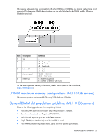
• DIMM configuration on channel 1 and channel 2 of a processor must be identical. • In multi-processor configurations, each processor must have a valid Lockstep Memory configuration. • In multi-processor configurations, each processor may have a different valid Lockstep Memory configuration. Single-processor Lockstep population order For Lockstep memory mode configurations with a single processor, populate the DIMM slots in the following order: • RDIMM o First: A and B o Next: D and E o Do not populate slots C or F. • UDIMM o First: A and B o Last: D and E o Do not populate slots C or F. After installing the DIMMs, use RBSU to configure the system for Lockstep memory support. Multi-processor Lockstep population order For Lockstep memory mode configurations with multiple processors, populate the DIMM slots for each processor in the following order: • RDIMM o First: A and B o Next: D and E o Do not populate slots C or F. • UDIMM o First: A and B o Last: D and E o Do not populate slots C or F. After installing the DIMMs, use RBSU to configure the system for Lockstep memory support. Installing DIMMs CAUTION: To avoid damage to the hard drives, memory, and other system components, the air baffle, drive blanks, and access panel must be installed when the server is powered up. 1. Power down the server (on page 7). 2. For ML110 G6 servers, extend the server from the rack. 3. For ML150 G6 servers, do one of the following: o Unlock and remove the bezel ("Remove the tower bezel (ML150 G6 servers)" on page 8). Hardware options installation 28
-
 1
1 -
2
-
3
-
4
-
5
-
6
-
7
-
8
-
9
-
10
-
11
-
12
-
13
-
14
-
15
-
16
-
17
-
18
-
19
-
20
-
21
-
22
-
 23
23 -
 24
24 -
 25
25 -
 26
26 -
 27
27 -
 28
28 -
 29
29 -
 30
30 -
 31
31 -
 32
32 -
 33
33 -
34
-
35
-
36
-
37
-
38
-
39
-
40
-
41
-
42
-
43
-
44
-
45
-
46
-
47
-
48
-
49
-
50
-
51
-
52
-
53
-
54
-
55
-
56
-
57
-
58
-
59
-
60
-
61
-
62
-
63
-
64
-
65
-
66
-
67
-
68
-
69
-
70
-
71
-
72
-
73
-
74
-
75
-
76
-
77
-
78
-
79
-
80
-
81
-
82
-
83
-
84
-
85
-
86
-
87
-
88
-
89
-
90
-
91
-
92
-
93
-
94
-
95
-
96
-
97
-
98
-
99
-
100
-
101
-
102
-
103
-
104
-
105
-
106
-
107
-
108
-
109
-
110
-
111
-
112
 |
 |