HP ML150 HP ProLiant ML100 Series Server User Guide - Page 32
Installing a storage controller, Battery-backed write cache battery pack option - g6 raid 5
 |
UPC - 884420743644
View all HP ML150 manuals
Add to My Manuals
Save this manual to your list of manuals |
Page 32 highlights
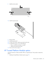
14. Power up the server (on page 7). Installing a storage controller IMPORTANT: For additional installation and configuration information, refer to the documentation that ships with the option. To install the component: 1. Power down the server (on page 7). 2. For ML110 G6 servers, extend the server from the rack. 3. For ML150 G6 servers, do one of the following: o Unlock and remove the bezel ("Remove the tower bezel (ML150 G6 servers)" on page 8). o Extend the server from the rack. 4. Remove the server from the rack. 5. Remove the access panel (on page 7). 6. For ML150 G6 servers, remove the PCI riser board assembly. For instructions, see the server installation sheet. 7. For ML150 G6 servers, remove the hard drive cables. 8. Install the storage controller into a full-height/full-length PCIe2 x16 expansion slot ("Expansion board options" on page 29). For server-specific instructions, see the server installation sheet. 9. Connect the storage controller cable to the controller and to the hard drive. For server-specific instructions, see the server installation sheet and the documentation that ships with the storage controller. IMPORTANT: The server does not power up if the PCI riser board assembly is not seated properly. 10. For ML150 G6 servers, install the PCI riser board assembly. For server-specific instructions, see the server installation sheet and the documentation that ships with the storage controller. 11. Install the access panel. 12. For ML110 G6 servers, slide the server back into the rack 13. For ML150 G6 servers, do one of the following: o Close or install the tower bezel, as needed. o Slide the server back into the rack. 14. Power up the server (on page 7). Battery-backed write cache battery pack option CAUTION: To prevent a server malfunction or damage to the equipment, do not add or remove the battery pack while an array capacity expansion, RAID level migration, or stripe size migration is in progress. Hardware options installation 32
-
 1
1 -
2
-
3
-
4
-
5
-
6
-
7
-
8
-
9
-
10
-
11
-
12
-
13
-
14
-
15
-
16
-
17
-
18
-
19
-
20
-
21
-
22
-
23
-
24
-
25
-
26
-
 27
27 -
 28
28 -
 29
29 -
 30
30 -
 31
31 -
 32
32 -
 33
33 -
 34
34 -
 35
35 -
 36
36 -
 37
37 -
38
-
39
-
40
-
41
-
42
-
43
-
44
-
45
-
46
-
47
-
48
-
49
-
50
-
51
-
52
-
53
-
54
-
55
-
56
-
57
-
58
-
59
-
60
-
61
-
62
-
63
-
64
-
65
-
66
-
67
-
68
-
69
-
70
-
71
-
72
-
73
-
74
-
75
-
76
-
77
-
78
-
79
-
80
-
81
-
82
-
83
-
84
-
85
-
86
-
87
-
88
-
89
-
90
-
91
-
92
-
93
-
94
-
95
-
96
-
97
-
98
-
99
-
100
-
101
-
102
-
103
-
104
-
105
-
106
-
107
-
108
-
109
-
110
-
111
-
112
 |
 |