HP SW TL881 DLT Mini-Lib/1 Compaq StorageWorks TL881/TL891 Family MiniLibrary - Page 100
Installing the PTM in the Rack
 |
View all HP SW TL881 DLT Mini-Lib/1 manuals
Add to My Manuals
Save this manual to your list of manuals |
Page 100 highlights
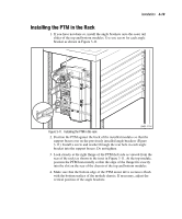
Installation 3-19 Installing the PTM in the Rack 1. If you have not done so, install the angle brackets onto the outer rail slides of the top and bottom modules. Use one screw for each angle bracket as shown in Figure 3-11. SHR-1714 Figure 3-11. Installing the PTM in the rack 2. Position the PTM against the back of the installed modules so that the support braces rest on the previously installed angle brackets (Figure 3-11). Install a screw and washer through the rear hole in each angle bracket into the support braces. Do not tighten. 3. Look closely at the right flange of the PTM (left side as viewed from the rear of the rack) as shown in the inset in Figure 3-11. At the top module, position the PTM horizontally so that the edge of the flange fits exactly into the slot on the rear of the chassis of the top and bottom modules. 4. Make sure that the bottom edge of the PTM motor drive section is flush with the bottom surface of the module chassis. If necessary, adjust the vertical position of the angle brackets.
-
 1
1 -
2
-
3
-
4
-
5
-
6
-
7
-
8
-
9
-
10
-
11
-
12
-
13
-
14
-
15
-
16
-
17
-
18
-
19
-
20
-
21
-
22
-
23
-
24
-
25
-
26
-
27
-
28
-
29
-
30
-
31
-
32
-
33
-
34
-
35
-
36
-
37
-
38
-
39
-
40
-
41
-
42
-
43
-
44
-
45
-
46
-
47
-
48
-
49
-
50
-
51
-
52
-
53
-
54
-
55
-
56
-
57
-
58
-
59
-
60
-
61
-
62
-
63
-
64
-
65
-
66
-
67
-
68
-
69
-
70
-
71
-
72
-
73
-
74
-
75
-
76
-
77
-
78
-
79
-
80
-
81
-
82
-
83
-
84
-
85
-
86
-
87
-
88
-
89
-
90
-
91
-
92
-
93
-
94
-
 95
95 -
 96
96 -
 97
97 -
 98
98 -
 99
99 -
 100
100 -
 101
101 -
 102
102 -
 103
103 -
 104
104 -
 105
105 -
106
-
107
-
108
-
109
-
110
-
111
-
112
-
113
-
114
-
115
-
116
-
117
-
118
-
119
-
120
-
121
-
122
-
123
-
124
-
125
-
126
-
127
-
128
-
129
-
130
-
131
-
132
-
133
-
134
-
135
-
136
-
137
-
138
-
139
-
140
-
141
-
142
-
143
-
144
-
145
-
146
-
147
-
148
-
149
-
150
-
151
-
152
-
153
-
154
-
155
-
156
-
157
-
158
-
159
-
160
-
161
-
162
-
163
-
164
-
165
-
166
-
167
-
168
-
169
-
170
-
171
-
172
-
173
-
174
-
175
-
176
-
177
-
178
-
179
-
180
-
181
-
182
-
183
-
184
-
185
-
186
-
187
-
188
-
189
-
190
-
191
-
192
-
193
-
194
-
195
-
196
-
197
-
198
-
199
-
200
-
201
-
202
-
203
-
204
-
205
-
206
-
207
-
208
-
209
-
210
-
211
-
212
-
213
 |
 |
