HP SW TL881 DLT Mini-Lib/1 Compaq StorageWorks TL881/TL891 Family MiniLibrary - Page 110
Configuration, Table 3-10, Base Module SCSI Connectors, Terminator, Jumpers, and Cables
 |
View all HP SW TL881 DLT Mini-Lib/1 manuals
Add to My Manuals
Save this manual to your list of manuals |
Page 110 highlights
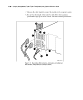
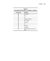
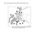
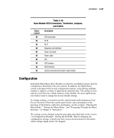
Installation 3-29 Table 3-10 Base Module SCSI Connectors, Terminator, Jumpers, and Cables Figure Legend 1 2 3 4 5 6 7 8 9 : Description SCSI terminator DLT0 DLT1 Expansion unit interface Power connector Power cable Fan SCSI jumpers SCSI interface Library connectors (not used in slave mode) Configuration Individual MiniLibrary Base Modules in all newly assembled systems must be configured as described in the next section. In addition, the MiniLibrary system is designed with several configuration options, each offering multiple settings to support a variety of applications and platforms. The setting of each option is stored in non-volatile memory in the module. For most applications, you will not need to change the factory default settings. To change settings, you need to use the control panel on the Expansion Unit. For an overview of how the control panel works, and a description of the functions of the buttons, indicators and display, see the sections, "Entering the Menu Mode," "Exiting the Menu Mode," and "Navigating Through the Menu Structure," in Chapter 2, "Operation." The settings can be changed using the procedure described later in the section "A Configuration Example - Setting the SCSI ID." Before changing any configuration settings, consult your host system documentation to determine which settings might need to be changed.
-
 1
1 -
2
-
3
-
4
-
5
-
6
-
7
-
8
-
9
-
10
-
11
-
12
-
13
-
14
-
15
-
16
-
17
-
18
-
19
-
20
-
21
-
22
-
23
-
24
-
25
-
26
-
27
-
28
-
29
-
30
-
31
-
32
-
33
-
34
-
35
-
36
-
37
-
38
-
39
-
40
-
41
-
42
-
43
-
44
-
45
-
46
-
47
-
48
-
49
-
50
-
51
-
52
-
53
-
54
-
55
-
56
-
57
-
58
-
59
-
60
-
61
-
62
-
63
-
64
-
65
-
66
-
67
-
68
-
69
-
70
-
71
-
72
-
73
-
74
-
75
-
76
-
77
-
78
-
79
-
80
-
81
-
82
-
83
-
84
-
85
-
86
-
87
-
88
-
89
-
90
-
91
-
92
-
93
-
94
-
95
-
96
-
97
-
98
-
99
-
100
-
101
-
102
-
103
-
104
-
 105
105 -
 106
106 -
 107
107 -
 108
108 -
 109
109 -
 110
110 -
 111
111 -
 112
112 -
 113
113 -
 114
114 -
 115
115 -
116
-
117
-
118
-
119
-
120
-
121
-
122
-
123
-
124
-
125
-
126
-
127
-
128
-
129
-
130
-
131
-
132
-
133
-
134
-
135
-
136
-
137
-
138
-
139
-
140
-
141
-
142
-
143
-
144
-
145
-
146
-
147
-
148
-
149
-
150
-
151
-
152
-
153
-
154
-
155
-
156
-
157
-
158
-
159
-
160
-
161
-
162
-
163
-
164
-
165
-
166
-
167
-
168
-
169
-
170
-
171
-
172
-
173
-
174
-
175
-
176
-
177
-
178
-
179
-
180
-
181
-
182
-
183
-
184
-
185
-
186
-
187
-
188
-
189
-
190
-
191
-
192
-
193
-
194
-
195
-
196
-
197
-
198
-
199
-
200
-
201
-
202
-
203
-
204
-
205
-
206
-
207
-
208
-
209
-
210
-
211
-
212
-
213
 |
 |
