HP SW TL881 DLT Mini-Lib/1 Compaq StorageWorks TL881/TL891 Family MiniLibrary - Page 104
Interface Cable, have at least one SCSI controller and the appropriate driver software. As noted
 |
View all HP SW TL881 DLT Mini-Lib/1 manuals
Add to My Manuals
Save this manual to your list of manuals |
Page 104 highlights
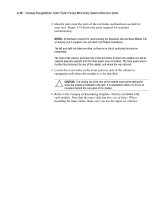
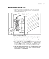
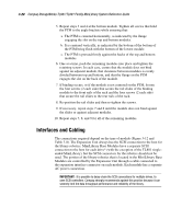
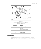
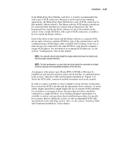
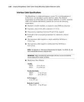
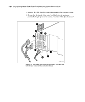
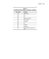
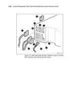
Installation 3-23 In the MiniLibrary Base Module, each drive is wired to an independent bus with a pair of SCSI connectors. Because it can be used in free-standing applications, the MiniLibrary Base Module has a pair of SCSI connectors for that module's library robotics. The library robotics SCSI interface should not be connected when installed in a system with an Expansion Unit. The Expansion Unit controls the library robotics for all of the modules in the system. It has a single SCSI bus, with a pair of SCSI connectors, to enable a host to control the library robotics. Each of the drives in the system and the library robotics is a separate SCSI device and is wired to a separate SCSI bus. Any of the separate buses can be combined using a SCSI jumper cable, available from Compaq. If any two or more devices are connected to the same SCSI bus, each must be assigned a unique SCSI address. For information on assigning SCSI addresses, see the section, "Configuration," later in this chapter. NOTE: For reduced internal cable length the single-ended units have the robotics and first drive daisy-chained internally. NOTE: For best performance, no more than two drives should be connected to a single SCSI bus, because of the bandwidth limitations of the SCSI bus. A terminator of the proper type (68-pin HVD, LVD/SE or SE) must be installed on each unused connector at the end of each bus, as explained below in the section, "Interface Cable and Terminator Installation." Figure 3-12 shows the SCSI cable, connectors and bus terminator used on the module. In order to connect a module to a host computer system, the host system must have at least one SCSI controller and the appropriate driver software. As noted earlier, higher-speed drives might require the use of separate SCSI controllers for each drive or each pair of drives. No more than two drives should be connected to a single SCSI bus. Your Technical Support representative is available to answer your questions about installation procedures for specific host systems. Before cabling the system, see the recommended SCSI cable specifications in the following section. Also, see the section, "Interface Cable and Terminator Installation" in this chapter.
-
 1
1 -
2
-
3
-
4
-
5
-
6
-
7
-
8
-
9
-
10
-
11
-
12
-
13
-
14
-
15
-
16
-
17
-
18
-
19
-
20
-
21
-
22
-
23
-
24
-
25
-
26
-
27
-
28
-
29
-
30
-
31
-
32
-
33
-
34
-
35
-
36
-
37
-
38
-
39
-
40
-
41
-
42
-
43
-
44
-
45
-
46
-
47
-
48
-
49
-
50
-
51
-
52
-
53
-
54
-
55
-
56
-
57
-
58
-
59
-
60
-
61
-
62
-
63
-
64
-
65
-
66
-
67
-
68
-
69
-
70
-
71
-
72
-
73
-
74
-
75
-
76
-
77
-
78
-
79
-
80
-
81
-
82
-
83
-
84
-
85
-
86
-
87
-
88
-
89
-
90
-
91
-
92
-
93
-
94
-
95
-
96
-
97
-
98
-
 99
99 -
 100
100 -
 101
101 -
 102
102 -
 103
103 -
 104
104 -
 105
105 -
 106
106 -
 107
107 -
 108
108 -
 109
109 -
110
-
111
-
112
-
113
-
114
-
115
-
116
-
117
-
118
-
119
-
120
-
121
-
122
-
123
-
124
-
125
-
126
-
127
-
128
-
129
-
130
-
131
-
132
-
133
-
134
-
135
-
136
-
137
-
138
-
139
-
140
-
141
-
142
-
143
-
144
-
145
-
146
-
147
-
148
-
149
-
150
-
151
-
152
-
153
-
154
-
155
-
156
-
157
-
158
-
159
-
160
-
161
-
162
-
163
-
164
-
165
-
166
-
167
-
168
-
169
-
170
-
171
-
172
-
173
-
174
-
175
-
176
-
177
-
178
-
179
-
180
-
181
-
182
-
183
-
184
-
185
-
186
-
187
-
188
-
189
-
190
-
191
-
192
-
193
-
194
-
195
-
196
-
197
-
198
-
199
-
200
-
201
-
202
-
203
-
204
-
205
-
206
-
207
-
208
-
209
-
210
-
211
-
212
-
213
 |
 |