HP Tc2120 serhp server tc2120 operations and maintenance guide - english - Page 23
Heading2 - Mass Storage Guidelines, IDE Devices
 |
UPC - 808736945332
View all HP Tc2120 manuals
Add to My Manuals
Save this manual to your list of manuals |
Page 23 highlights
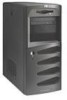
Chapter 3 Installing and Configuring Please refer to the appropriate topics listed in this section according to your server configuration (IDE or SCSI). Shelf 1 (FDD) Shelf 2 (CD-ROM) Shelf 3 (Optional CD-ROM, DVD Drive, or Backup Tape Drive) Shelf 4 (3rd Hard Drive-Optional) Drive Retaining Clips Shelf 5 (1st Hard Drive-Standard) Shelf 6 (2nd Hard Drive-Optional) Figure 3-5. Mass Storage Locations Mass Storage Guidelines • General Guidelines o Use care when unpacking and handling the hard disk drives. The hard disk drives are very susceptible to mechanical shock and can be easily damaged by a drop as short as one-quarter of an inch. If the drop would crack an egg, it will damage the drive. o Do not stack drives. o The server is internally limited to 6 mass storage shelves. The flexible disk drive and CD-ROM drive, which are standard on all models of the hp server tc2120, occupy shelves 1 and 2 respectively. The first four mass storage shelves may also be referred to as common trays, or drive trays. See Figure 3-5. • IDE Devices o The embedded IDE controller is an Enhanced-IDE dual channel controller and provides two connectors (IDE-1 and IDE-2) for IDE devices. Refer to "System Board Layout" in Chapter 9, Specifications. o The IDE CD-ROM uses one connector on the cable from the IDE-2 connector, leaving one connector for an optional third hard drive or IDE device on the IDE model. The CD-ROM is configured as the master device, unless a third HDD is installed, which should be configured as the master device. For the SCSI model the second IDE-2 connector could be used for any additional IDE device, such as IDE hard drive. o The primary IDE connector (IDE-1) and cable is used for the first or standard hard IDE drive and the second optional hard drive. 17
-
 1
1 -
2
-
3
-
4
-
5
-
6
-
7
-
8
-
9
-
10
-
11
-
12
-
13
-
14
-
15
-
16
-
17
-
 18
18 -
 19
19 -
 20
20 -
 21
21 -
 22
22 -
 23
23 -
 24
24 -
 25
25 -
 26
26 -
 27
27 -
 28
28 -
29
-
30
-
31
-
32
-
33
-
34
-
35
-
36
-
37
-
38
-
39
-
40
-
41
-
42
-
43
-
44
-
45
-
46
-
47
-
48
-
49
-
50
-
51
-
52
-
53
-
54
-
55
-
56
-
57
-
58
-
59
-
60
-
61
-
62
-
63
-
64
-
65
-
66
-
67
-
68
-
69
-
70
-
71
-
72
-
73
-
74
-
75
-
76
-
77
-
78
-
79
-
80
-
81
-
82
-
83
-
84
-
85
-
86
-
87
-
88
-
89
-
90
-
91
-
92
-
93
-
94
-
95
-
96
-
97
-
98
-
99
-
100
-
101
-
102
-
103
-
104
-
105
-
106
-
107
-
108
-
109
-
110
-
111
-
112
-
113
-
114
-
115
-
116
-
117
-
118
-
119
-
120
-
121
-
122
-
123
-
124
-
125
 |
 |
