HP Tc2120 serhp server tc2120 operations and maintenance guide - english - Page 63
Heading1 - Clearing the CMOS and Passwords, ROM initialization. Contact your HP Customer Support - ram
 |
UPC - 808736945332
View all HP Tc2120 manuals
Add to My Manuals
Save this manual to your list of manuals |
Page 63 highlights
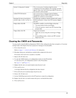
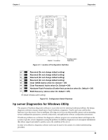
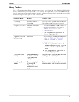
Chapter 4 Diagnostics System Configuration Updated Update DMI Information Warning! PCI device has failed to initialize (Bus: xx Dev: yy Fun: zz ) Floppy disk(s) fail (80) Floppy disk(s) fail (40) This is not an error. It indicates that the system configuration has been updated. This message normally appears when a new device has been added to the server. No corrective action needed. This is not an error. It indicates that the Desktop Management Interface (DMI) information has been updated. No corrective action needed. The BIOS has insufficient shadow RAM for PCI option ROM initialization. Contact your HP Customer Support provider. The BIOS is unable to reset the floppy subsystem. 1. Try using another known good floppy. 2. If the error persists, contact your HP Customer Support provider. Floppy type mismatch. 1. Make sure you are using the correct type of floppy disk. 2. If the problem persists, contact your HP Customer Support provider. Clearing the CMOS and Passwords You may need to clear the BIOS configuration (CMOS) if the configuration has been corrupted, or if incorrect settings made in the Setup Utility have caused error messages to be unreadable. 1. Power down the server. Refer to Chapter 1, Controls and Indicators for instructions. 2. Disconnect the power cord and any external cables connected to the server. If necessary, label each one to expedite re-assembly. 3. Remove the left side cover. 4. To clear the CMOS memory, set configuration switch 4 to the ON position. To clear passwords, set configuration switch 3 to the ON position. See Figure 4-1 and Figure 4-2. 5. Replace the left side cover and reconnect only the power cord. 6. Power up the server. A message indicates that the configuration has been cleared. 7. Power down the server and disconnect the power cord. 8. Remove the left side cover. 9. Set the CMOS/Password switch to the OFF position to retain the configuration. 10. Replace the left side cover and reconnect the power cord and all data cables. 11. Power up the server. 57
-
 1
1 -
2
-
3
-
4
-
5
-
6
-
7
-
8
-
9
-
10
-
11
-
12
-
13
-
14
-
15
-
16
-
17
-
18
-
19
-
20
-
21
-
22
-
23
-
24
-
25
-
26
-
27
-
28
-
29
-
30
-
31
-
32
-
33
-
34
-
35
-
36
-
37
-
38
-
39
-
40
-
41
-
42
-
43
-
44
-
45
-
46
-
47
-
48
-
49
-
50
-
51
-
52
-
53
-
54
-
55
-
56
-
57
-
 58
58 -
 59
59 -
 60
60 -
 61
61 -
 62
62 -
 63
63 -
 64
64 -
 65
65 -
 66
66 -
 67
67 -
 68
68 -
69
-
70
-
71
-
72
-
73
-
74
-
75
-
76
-
77
-
78
-
79
-
80
-
81
-
82
-
83
-
84
-
85
-
86
-
87
-
88
-
89
-
90
-
91
-
92
-
93
-
94
-
95
-
96
-
97
-
98
-
99
-
100
-
101
-
102
-
103
-
104
-
105
-
106
-
107
-
108
-
109
-
110
-
111
-
112
-
113
-
114
-
115
-
116
-
117
-
118
-
119
-
120
-
121
-
122
-
123
-
124
-
125
 |
 |
