IBM 4560SLX User Guide - Page 83
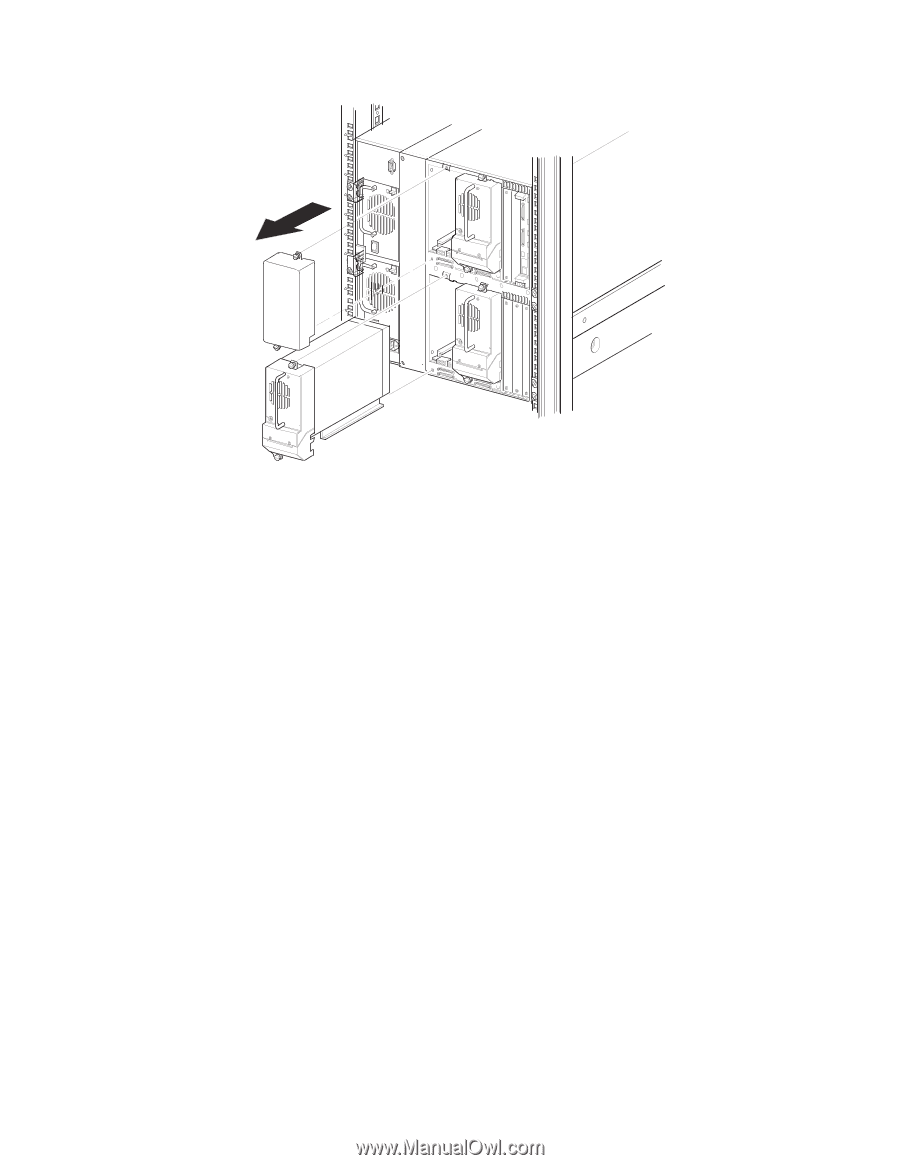
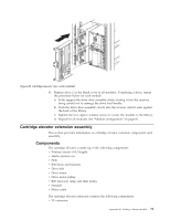
drive load handle has cleared the back of the library.
 |
UPC - 087944855910
View all IBM 4560SLX manuals
Add to My Manuals
Save this manual to your list of manuals |
Page 83 highlights
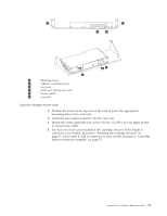
Figure 66. Drive shoe and blank panel removal Note: With a blank panel or tape drive removed, there is access to moving parts. DO NOT reach into open cavities. a. Loosen the captive retainer screws at the top center and lower left of the drive module. b. Pull straight back on the drive shoe handle to remove the drive. Some effort will be required to overcome the initial resistance of unplugging the module from the receiver. c. Continue to slide the drive out while fully supporting the module until the drive load handle has cleared the back of the library. 4. Remove the cover plate adjacent to the power supply as shown in Figure 67 on page 74. a. Remove two screws from the back of the cover plate. b. Remove two inner screws from inside the drive shoe slot. c. Remove top screw. Rack-mounted modules must be slid forward to access the top cover screw. Appendix B. Adding a library module 73
-
 1
1 -
2
-
3
-
4
-
5
-
6
-
7
-
8
-
9
-
10
-
11
-
12
-
13
-
14
-
15
-
16
-
17
-
18
-
19
-
20
-
21
-
22
-
23
-
24
-
25
-
26
-
27
-
28
-
29
-
30
-
31
-
32
-
33
-
34
-
35
-
36
-
37
-
38
-
39
-
40
-
41
-
42
-
43
-
44
-
45
-
46
-
47
-
48
-
49
-
50
-
51
-
52
-
53
-
54
-
55
-
56
-
57
-
58
-
59
-
60
-
61
-
62
-
63
-
64
-
65
-
66
-
67
-
68
-
69
-
70
-
71
-
72
-
73
-
74
-
75
-
76
-
77
-
 78
78 -
 79
79 -
 80
80 -
 81
81 -
 82
82 -
 83
83 -
 84
84 -
 85
85 -
 86
86 -
 87
87 -
 88
88 -
89
-
90
-
91
-
92
-
93
-
94
-
95
-
96
-
97
-
98
-
99
-
100
-
101
-
102
-
103
-
104
-
105
-
106
-
107
-
108
-
109
-
110
-
111
-
112
-
113
-
114
-
115
-
116
-
117
-
118
-
119
-
120
-
121
-
122
-
123
-
124
-
125
-
126
-
127
-
128
 |
 |