IBM 4560SLX User Guide - Page 90
to the appropriate size for the total number of modules used as shown
 |
UPC - 087944855910
View all IBM 4560SLX manuals
Add to My Manuals
Save this manual to your list of manuals |
Page 90 highlights
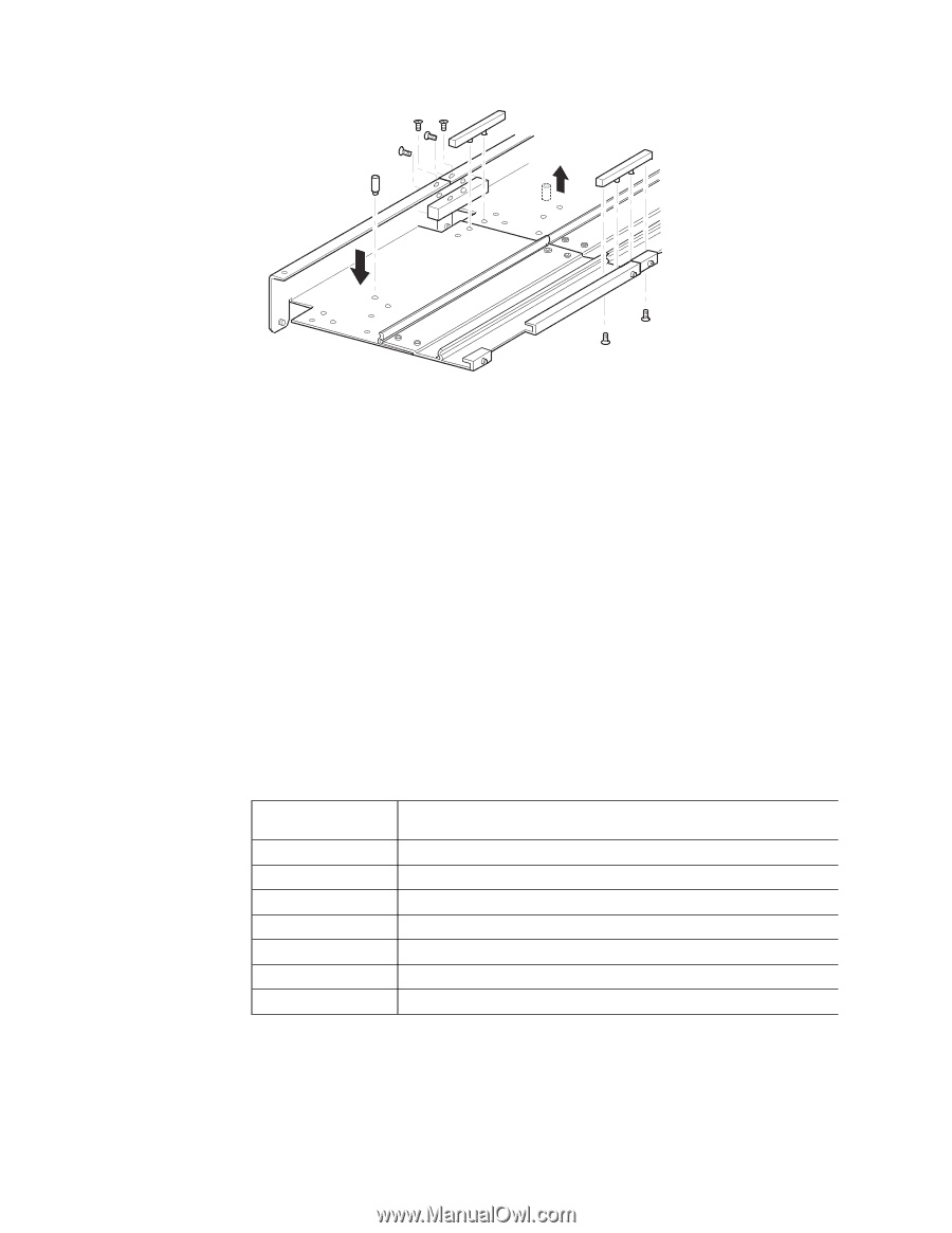
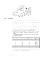
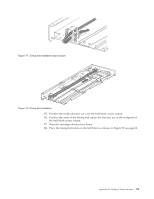
Figure 76. Tie bar installation c. Attach the large tie bars with the four mounting screws so that the beveled edge is facing the inside corner of the chassis and extension. 9. Remove the bottom stop standoff from the primary chassis and attach it to the cartridge elevator extension in the corresponding mounting hole as shown in Figure 76. 10. Attach the tensioner springs mounting hardware and springs. 11. Attach the tensioner ramp/idler pulley components to the cartridge elevator extension in the same manner as shown in Figure 74 on page 79. 12. On the tensioner ramp/idler pulley base of the base expansion section, compress the springs until the holes in the tensioner ramp are aligned with the holes in the base of the tensioner, and insert a 0.05 in. allen wrench through the holes. This sets the idler pulley to the zero position. 13. Cut the new timing belt supplied with the expansion kit (between the teeth) to the appropriate size for the total number of modules used as shown in Table 8. The timing belt supplied with the expansion kits is marked and numbered at the appropriate cut points. Table 8. Timing belt lengths Number of modules Number of teeth Length of belt (Centimeters) Length of belt (Inches) 2 169 85.8 33 13/16 3 257 130.6 51 3/8 4 344 174.8 68 13/16 5 432 219.5 86 3/8 6 519 263.6 103 13/16 7 607 308.4 121 3/8 8 694 352.6 138 13/16 14. Thread the timing belt counter-clockwise through the top of the tensioner ramp/idler pulley and clockwise through the motor drive pulley as shown in Figure 77 on page 81 and Figure 78 on page 81. 80 4560SLX Tape Library: User's Guide
-
 1
1 -
2
-
3
-
4
-
5
-
6
-
7
-
8
-
9
-
10
-
11
-
12
-
13
-
14
-
15
-
16
-
17
-
18
-
19
-
20
-
21
-
22
-
23
-
24
-
25
-
26
-
27
-
28
-
29
-
30
-
31
-
32
-
33
-
34
-
35
-
36
-
37
-
38
-
39
-
40
-
41
-
42
-
43
-
44
-
45
-
46
-
47
-
48
-
49
-
50
-
51
-
52
-
53
-
54
-
55
-
56
-
57
-
58
-
59
-
60
-
61
-
62
-
63
-
64
-
65
-
66
-
67
-
68
-
69
-
70
-
71
-
72
-
73
-
74
-
75
-
76
-
77
-
78
-
79
-
80
-
81
-
82
-
83
-
84
-
 85
85 -
 86
86 -
 87
87 -
 88
88 -
 89
89 -
 90
90 -
 91
91 -
 92
92 -
 93
93 -
 94
94 -
 95
95 -
96
-
97
-
98
-
99
-
100
-
101
-
102
-
103
-
104
-
105
-
106
-
107
-
108
-
109
-
110
-
111
-
112
-
113
-
114
-
115
-
116
-
117
-
118
-
119
-
120
-
121
-
122
-
123
-
124
-
125
-
126
-
127
-
128
 |
 |