IBM 4560SLX User Guide - Page 89
Align the tie bar pins of the two narrow tie bars to the holes in
 |
UPC - 087944855910
View all IBM 4560SLX manuals
Add to My Manuals
Save this manual to your list of manuals |
Page 89 highlights
Figure 74. Tensioner ramp/idler pulley 8. Mount the cartridge elevator extension: a. Insert alignment pins of the extension to the slot at the bottom of the primary chassis as shown in Figure 75. Figure 75. Cartridge elevator extension alignment b. Align the tie bar pins of the two narrow tie bars to the holes in the extension and primary chassis and attach with the four mounting screws (two each) as shown in Figure 76 on page 80. Appendix B. Adding a library module 79
-
 1
1 -
2
-
3
-
4
-
5
-
6
-
7
-
8
-
9
-
10
-
11
-
12
-
13
-
14
-
15
-
16
-
17
-
18
-
19
-
20
-
21
-
22
-
23
-
24
-
25
-
26
-
27
-
28
-
29
-
30
-
31
-
32
-
33
-
34
-
35
-
36
-
37
-
38
-
39
-
40
-
41
-
42
-
43
-
44
-
45
-
46
-
47
-
48
-
49
-
50
-
51
-
52
-
53
-
54
-
55
-
56
-
57
-
58
-
59
-
60
-
61
-
62
-
63
-
64
-
65
-
66
-
67
-
68
-
69
-
70
-
71
-
72
-
73
-
74
-
75
-
76
-
77
-
78
-
79
-
80
-
81
-
82
-
83
-
 84
84 -
 85
85 -
 86
86 -
 87
87 -
 88
88 -
 89
89 -
 90
90 -
 91
91 -
 92
92 -
 93
93 -
 94
94 -
95
-
96
-
97
-
98
-
99
-
100
-
101
-
102
-
103
-
104
-
105
-
106
-
107
-
108
-
109
-
110
-
111
-
112
-
113
-
114
-
115
-
116
-
117
-
118
-
119
-
120
-
121
-
122
-
123
-
124
-
125
-
126
-
127
-
128
 |
 |
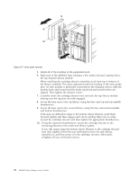
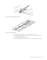
8.
Mount the cartridge elevator extension:
a.
Insert alignment pins of the extension to the slot at the bottom of the
primary chassis as shown in Figure 75.
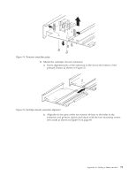
b.
Align the tie bar pins of the two narrow tie bars to the holes in the
extension and primary chassis and attach with the four mounting screws
(two each) as shown in Figure 76 on page 80.
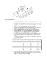
Figure 74. Tensioner ramp/idler pulley
Figure 75. Cartridge elevator extension alignment
Appendix B. Adding a library module
79