IBM 4560SLX User Guide - Page 95
Cabling and interface connections
 |
UPC - 087944855910
View all IBM 4560SLX manuals
Add to My Manuals
Save this manual to your list of manuals |
Page 95 highlights
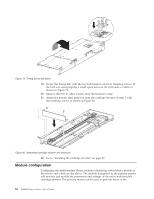
now controlled through the master. The missing options identify the module as a slave as shown in Figure 84. Figure 84. Module configured as a slave 8. Repeat step 1 through step 6 for all slave modules. 9. Using the touch screen, power off all modules, both master and slaves, after configuration and then switch the master power switch at the rear of each module to the off (0) position. 10. Verify that all modules are powered down. 11. Proceed to "Cabling and interface connections". Cabling and interface connections Before the cartridge elevator combination can communicate with the host device or user applications, the connections shown in Figure 85 on page 86 must be made. A four module library is used for illustration purposes. The second module (slave 0) has been selected as the secondary master. 1. Verify that the modules and router have been properly installed in the rack. Power down all the modules and the router. Appendix B. Adding a library module 85
-
 1
1 -
2
-
3
-
4
-
5
-
6
-
7
-
8
-
9
-
10
-
11
-
12
-
13
-
14
-
15
-
16
-
17
-
18
-
19
-
20
-
21
-
22
-
23
-
24
-
25
-
26
-
27
-
28
-
29
-
30
-
31
-
32
-
33
-
34
-
35
-
36
-
37
-
38
-
39
-
40
-
41
-
42
-
43
-
44
-
45
-
46
-
47
-
48
-
49
-
50
-
51
-
52
-
53
-
54
-
55
-
56
-
57
-
58
-
59
-
60
-
61
-
62
-
63
-
64
-
65
-
66
-
67
-
68
-
69
-
70
-
71
-
72
-
73
-
74
-
75
-
76
-
77
-
78
-
79
-
80
-
81
-
82
-
83
-
84
-
85
-
86
-
87
-
88
-
89
-
 90
90 -
 91
91 -
 92
92 -
 93
93 -
 94
94 -
 95
95 -
 96
96 -
 97
97 -
 98
98 -
 99
99 -
 100
100 -
101
-
102
-
103
-
104
-
105
-
106
-
107
-
108
-
109
-
110
-
111
-
112
-
113
-
114
-
115
-
116
-
117
-
118
-
119
-
120
-
121
-
122
-
123
-
124
-
125
-
126
-
127
-
128
 |
 |
