Icom IC-7200 Instruction Manual - Page 17
INSTALLATION AND CONNECTIONS, ■ Unpacking, ■ Selecting a location, ■ Grounding - problems
 |
View all Icom IC-7200 manuals
Add to My Manuals
Save this manual to your list of manuals |
Page 17 highlights
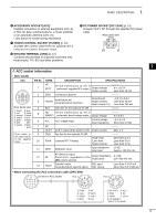
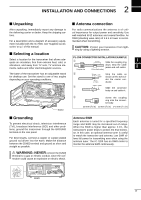
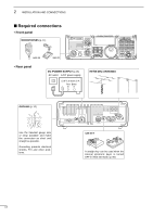
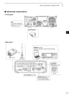
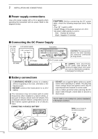
2 INSTALLATION AND CONNECTIONS ■ Unpacking ■ Antenna connection After unpacking, immediately report any damage to the delivering carrier or dealer. Keep the shipping cartons. For a description and a diagram of accessory equipment included with the IC-7200, see 'Supplied accessories' on p. i of this manual. For radio communications the antenna is of critical importance for output power and sensitivity. Use well-matched 50 ø antennas and coaxial feedline. An SWR (standing wave ratio) of 1.5:1 or lower is recommended when transmitting. CAUTION: Protect your transceiver from light- ning by using a lightning arrestor. ■ Selecting a location PL-259 CONNECTOR INSTALLATION EXAMPLE Select a location for the transceiver that allows adequate air circulation, free from extreme heat, cold, or q 1 30 mm Slide the coupling ring vibrations, and away from TV sets, TV antenna elements, radios and other electromagnetic sources. down. Strip the cable jacket and soft solder. 2 Coupling ring 10 mm (soft solder) The base of the transceiver has an adjustable stand w for desktop use. Set the stand to one of two angles depending on your operating conditions. 3 10 mm Soft Strip the cable as solder shown at left. Soft solder the center con- 4 1-2 mm ductor. e solder solder 5 Slide the connector body on and solder it. 6 r Screw the coupling 7 ring onto the connector body. 8 Stand 30 mm (9⁄8 in) 10 mm (3⁄8 in) 1-2 mm (1⁄16 in) 9 10 ■ Grounding Antenna SWR Each antenna is tuned for a specified frequency 11 To prevent electrical shock, television interference range and SWR may be increased out-of-range. (TVI), broadcast interference (BCI) and other prob- When the SWR is higher than approx. 2.0:1, the 12 lems, ground the transceiver through the GROUND transceiver's power drops to protect the final transis- terminal on the rear panel. tor. In this case, an optional antenna tuner is useful 13 to match the transceiver and antenna. Low SWR al- For best results, connect a copper or copper-plated ground rod driven into the earth. Make the distance lows full power for transmitting even when using the antenna tuner. The IC-7200 has an SWR meter to 14 between the [GND] terminal and ground as short and straight as possible. monitor the antenna SWR continuously. 15 R WARNING: NEVER connect the [GND] 16 terminal to a gas or electric conduit, since the connection could cause an explosion or electric shock. 17 18 19 20 [GND] 21 12
-
 1
1 -
2
-
3
-
4
-
5
-
6
-
7
-
8
-
9
-
10
-
11
-
 12
12 -
 13
13 -
 14
14 -
 15
15 -
 16
16 -
 17
17 -
 18
18 -
 19
19 -
 20
20 -
 21
21 -
 22
22 -
23
-
24
-
25
-
26
-
27
-
28
-
29
-
30
-
31
-
32
-
33
-
34
-
35
-
36
-
37
-
38
-
39
-
40
-
41
-
42
-
43
-
44
-
45
-
46
-
47
-
48
-
49
-
50
-
51
-
52
-
53
-
54
-
55
-
56
-
57
-
58
-
59
-
60
-
61
-
62
-
63
-
64
-
65
-
66
-
67
-
68
-
69
-
70
-
71
-
72
-
73
-
74
-
75
-
76
-
77
-
78
-
79
-
80
-
81
-
82
-
83
-
84
-
85
-
86
-
87
-
88
-
89
-
90
-
91
-
92
-
93
-
94
-
95
-
96
-
97
-
98
-
99
-
100
-
101
-
102
-
103
-
104
 |
 |
