Icom IC-7200 Instruction Manual - Page 96
◇ Band stacking register, ◇ Data mode with filter width setting, FREQUENCY RANGE
 |
View all Icom IC-7200 manuals
Add to My Manuals
Save this manual to your list of manuals |
Page 96 highlights
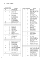
14 CONTROL COMMAND D Band stacking register To send or read the desired band stacking register's contents, a combination of the frequency band and the register codes ("01" is fixed as the register code) as follows are used. For example, when sending/reading the contents in the 21 MHz band, the code "0701" is used. • Frequency band codes CODE BAND FREQUENCY RANGE 01 1.8 MHz 1.800000 - 1.999999 02 3.5 MHz 3.400000 - 4.099999 03 7 MHz 6.900000 - 7.499999 04 10 MHz 9.900000 - 10.499999 05 14 MHz 13.900000 - 14.499999 06 18 MHz 17.900000 - 18.499999 07 21 MHz 20.900000 - 21.499999 08 24 MHz 24.400000 - 25.099999 09 28 MHz 28.000000 - 29.999999 10 50 MHz 50.000000 - 54.000000 11 General Other than above D Data mode with filter width setting The following data sequence is used when sending or reading the data mode with filter width setting. qw X XX X First parameter 00=Data mode OFF 01=Data mode ON Second parameter 00=Data mode OFF 01=FILTER Wide 02=FILTER Middle 03=FILTER Narrow 91
-
 1
1 -
2
-
3
-
4
-
5
-
6
-
7
-
8
-
9
-
10
-
11
-
12
-
13
-
14
-
15
-
16
-
17
-
18
-
19
-
20
-
21
-
22
-
23
-
24
-
25
-
26
-
27
-
28
-
29
-
30
-
31
-
32
-
33
-
34
-
35
-
36
-
37
-
38
-
39
-
40
-
41
-
42
-
43
-
44
-
45
-
46
-
47
-
48
-
49
-
50
-
51
-
52
-
53
-
54
-
55
-
56
-
57
-
58
-
59
-
60
-
61
-
62
-
63
-
64
-
65
-
66
-
67
-
68
-
69
-
70
-
71
-
72
-
73
-
74
-
75
-
76
-
77
-
78
-
79
-
80
-
81
-
82
-
83
-
84
-
85
-
86
-
87
-
88
-
89
-
90
-
 91
91 -
 92
92 -
 93
93 -
 94
94 -
 95
95 -
 96
96 -
 97
97 -
 98
98 -
 99
99 -
 100
100 -
 101
101 -
102
-
103
-
104
 |
 |
