Icom IC-7200 Instruction Manual - Page 18
■ Required connections, HF/50 MHz ANTENNA, DC POWER SUPPLY - tuner
 |
View all Icom IC-7200 manuals
Add to My Manuals
Save this manual to your list of manuals |
Page 18 highlights
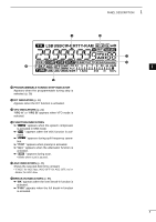
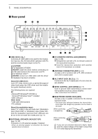
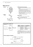
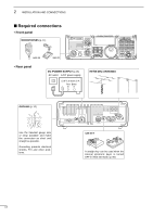
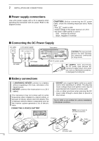
2 INSTALLATION AND CONNECTIONS ■ Required connections • Front panel MICROPHONES (p. 11) i72 00 HM-36 • Rear panel SM-20 DC POWER SUPPLY (p.15) AC outlet A DC power supply 13.8 V; at least 22 A Red Black +_ MODE TS TUNER FILTER SPCH NB NR ANF METER V/M 1 1.8 A=/B 2 3.5 SPLIT 3 7 MW 4 10 M-CL 5 14 AGC 6 18 COMP271 . RIT GENE SCAN 8 24 MNF 0 50 VOX 9 28 F-INP ENT BAND P.AMP ATT M-CH/RIT SET HF/50 MHz ANTENNA GROUND (p. 12) Use the heaviest gauge wire or strap available and make the connection as short and straight as possible. Grounding prevents electrical shocks, TVI and other problems. CW KEY A straight key can be used when the internal electronic keyer is turned OFF in initial set mode. (p. 80) 13
-
 1
1 -
2
-
3
-
4
-
5
-
6
-
7
-
8
-
9
-
10
-
11
-
12
-
 13
13 -
 14
14 -
 15
15 -
 16
16 -
 17
17 -
 18
18 -
 19
19 -
 20
20 -
 21
21 -
 22
22 -
 23
23 -
24
-
25
-
26
-
27
-
28
-
29
-
30
-
31
-
32
-
33
-
34
-
35
-
36
-
37
-
38
-
39
-
40
-
41
-
42
-
43
-
44
-
45
-
46
-
47
-
48
-
49
-
50
-
51
-
52
-
53
-
54
-
55
-
56
-
57
-
58
-
59
-
60
-
61
-
62
-
63
-
64
-
65
-
66
-
67
-
68
-
69
-
70
-
71
-
72
-
73
-
74
-
75
-
76
-
77
-
78
-
79
-
80
-
81
-
82
-
83
-
84
-
85
-
86
-
87
-
88
-
89
-
90
-
91
-
92
-
93
-
94
-
95
-
96
-
97
-
98
-
99
-
100
-
101
-
102
-
103
-
104
 |
 |

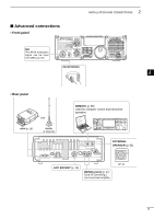
■
Required connections
• Front panel
i7200
MODE
TUNER
TS
FILTER
SPCH
V/M
A/B
SPLIT
M-CL
SCAN
SET
ATT
P
.
AMP
COMP
VOX
MNF
RIT
1
2
3
4
5
6
7
8
0
50
28
18
14
10
21
24
=
7
3.5
1.8
F-INP
M-CH/RIT
ENT
BAND
GENE
9
.
AGC
MW
ANF
METER
NR
NB
MICROPHONES
(p. 11)
SM-20
HM-36
• Rear panel
GROUND
(p. 12)
Use the heaviest gauge wire
or strap available and make
the connection as short and
straight as possible.
Grounding prevents electrical
shocks, TVI and other prob-
lems.
CW KEY
A straight key can be used when the
internal electronic keyer is turned
OFF in initial set mode. (p. 80)
HF/50 MHz ANTENNA
DC POWER SUPPLY
(p.15)
A DC power supply
AC outlet
13.8 V; at least 22 A
Black
_
Red
+
13
2
INSTALLATION AND CONNECTIONS