Intel BB5520UR Product Specification - Page 125
Front Panel Connector
 |
View all Intel BB5520UR manuals
Add to My Manuals
Save this manual to your list of manuals |
Page 125 highlights
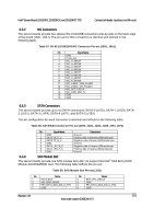
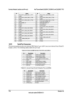
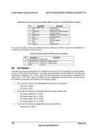
Intel® Server Boards S5520HC, S5500HCV, and S5520HCT TPS Connector/Header Locations and Pin-outs Pin Signal Name 27 3V3_AUX 29 GND 31 GND 33 GND 6.3.2 LCP/IPMB Header Pin 28 30 32 34 SPI_DO SPI_CLK SPI_DI Signal Name RMM3_Present_N (pulled high on baseboard and shorted to ground on the plug-in module) Table 52. LCP/IPMB Header Pin-out (J1G6) 6.3.3 Pin Signal Name 1 SMB_IPMB_5VSB_DAT 2 GND 3 SMB_IPMB_5VSB_CLK 4 P5V_STBY HSBP Header Description BMC IMB 5 V standby data line Ground BMC IMB 5 V standby clock line +5 V standby power Table 53. HSBP Header Pin-out (J1F5, J1G3) 6.3.4 Pin Signal Name 1 SMB_IPMB_5V_DAT 2 GND 3 SMB_IPMB_5V_CLK 4 P5V - HSBP_A GND - HSBP_B SGPIO Header Description BMC IMB 5 V Data Line Ground BMC IMB 5V Clock Line +5 V for HSBP A Ground for HSBP B Table 54. SGPIO Header Pin-out (J1G2) Pin Signal Name 1 SGPIO_CLOCK 2 SGPIO_LOAD 3 SGPIO_DATAOUT0 4 SGPIO_DATAOUT1 Description SGPIO Clock Signal SGPIO Load Signal SGPIO Data Out SGPIO Data In 6.4 Front Panel Connector The server boards provide a 24-pin SSI front panel connector (J1B3) for use with Intel® and third-party chassis. The following table provides the pin-out for this connector: Revision 1.8 111 Intel order number E39529-013
-
 1
1 -
2
-
3
-
4
-
5
-
6
-
7
-
8
-
9
-
10
-
11
-
12
-
13
-
14
-
15
-
16
-
17
-
18
-
19
-
20
-
21
-
22
-
23
-
24
-
25
-
26
-
27
-
28
-
29
-
30
-
31
-
32
-
33
-
34
-
35
-
36
-
37
-
38
-
39
-
40
-
41
-
42
-
43
-
44
-
45
-
46
-
47
-
48
-
49
-
50
-
51
-
52
-
53
-
54
-
55
-
56
-
57
-
58
-
59
-
60
-
61
-
62
-
63
-
64
-
65
-
66
-
67
-
68
-
69
-
70
-
71
-
72
-
73
-
74
-
75
-
76
-
77
-
78
-
79
-
80
-
81
-
82
-
83
-
84
-
85
-
86
-
87
-
88
-
89
-
90
-
91
-
92
-
93
-
94
-
95
-
96
-
97
-
98
-
99
-
100
-
101
-
102
-
103
-
104
-
105
-
106
-
107
-
108
-
109
-
110
-
111
-
112
-
113
-
114
-
115
-
116
-
117
-
118
-
119
-
 120
120 -
 121
121 -
 122
122 -
 123
123 -
 124
124 -
 125
125 -
 126
126 -
 127
127 -
 128
128 -
 129
129 -
 130
130 -
131
-
132
-
133
-
134
-
135
-
136
-
137
-
138
-
139
-
140
-
141
-
142
-
143
-
144
-
145
-
146
-
147
-
148
-
149
-
150
-
151
-
152
-
153
-
154
-
155
-
156
-
157
-
158
-
159
-
160
-
161
-
162
-
163
-
164
-
165
-
166
-
167
-
168
-
169
-
170
-
171
-
172
-
173
-
174
-
175
-
176
-
177
-
178
-
179
-
180
-
181
-
182
-
183
-
184
-
185
-
186
-
187
-
188
-
189
-
190
 |
 |
