Intel BB5520UR Product Specification - Page 126
I/O Connectors
 |
View all Intel BB5520UR manuals
Add to My Manuals
Save this manual to your list of manuals |
Page 126 highlights
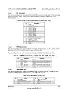
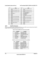
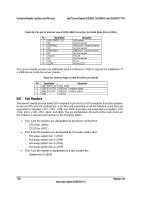
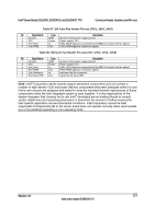
Connector/Header Locations and Pin-outs Intel® Server Boards S5520HC, S5500HCV, and S5520HCT TPS Table 55. Front Panel SSI Standard 24-pin Connector Pin-out (J1B3) Pin Signal Name Description Pin Signal Name Description 1 P3V3_STBY Power LED + 2 P3V3_STBY Front Panel (Power_LED_Anode) Power 3 Key No Connection 4 P5V_STBY (ID ID LED + LED Anode) 5 FP_PWR_LED_N Power LED - 6 FP_ID_LED_BU ID LED - F_N 7 P3V3 HDD Activity 8 FP_LED_STATU Status LED (HDD_ACTIVITY_Ano LED + S_GREEN_N Green - de) 9 LED_HDD_ACTIVITY HDD Activity 10 FP_LED_STATU Status LED _N LED - S_AMBER_N Amber - 11 FP_PWR_BTN_N Power Button 12 NIC1_ACT_LED NIC 1 Activity _N LED - 13 GND (Power Button Power Button 14 NIC1_LINK_LED NIC 1 Link GND) Ground _N LED - 15 BMC_RST_BTN_N Reset Button 16 SMB_SENSOR_ SMB Sensor 3V3STB_DATA DATA 17 BND (Reset GND) Reset Button 18 SMB_SENSOR_ SMB Sensor Ground 3V3STB_CLK Clock 19 FP_ID_BTN_N ID Button 20 FP_CHASSIS_IN Chassis TRU Intrusion 21 FM_SIO_TEMP_SEN Front Panel 22 NIC2_ACT_LED NIC 2 Activity SOR Temperature _N LED - Sensor 23 FP_NMI_BTN_N NMI Button 24 NIC2_LINK_LED NIC 2 Link _N LED - 6.5 I/O Connectors 6.5.1 VGA Connector The following table details the pin-out definition of the VGA connector (J7A1) that is part of the stacked video/serial port A connector. Table 56. VGA Connector Pin-out (J7A1) Pin Signal Name 1 V_IO_R_CONN 2 V_IO_G_CONN 3 V_IO_B_CONN 4 TP_VID_CONN_B4 5 GND 6 GND 7 GND 8 GND 9 TP_VID_CONN_B9 10 GND 11 TP_VID_CONN_B11 12 V_IO_DDCDAT 13 V_IO_HSYNC_CONN 14 V_IO_VSYNC_CONN 15 V_IO_DDCCLK Description Red (analog color signal R) Green (analog color signal G) Blue (analog color signal B) No connection Ground Ground Ground Ground No connection Ground No connection DDCDAT HSYNC (horizontal sync) VSYNC (vertical sync) DDCCLK 112 Revision 1.8 Intel order number E39529-013
-
 1
1 -
2
-
3
-
4
-
5
-
6
-
7
-
8
-
9
-
10
-
11
-
12
-
13
-
14
-
15
-
16
-
17
-
18
-
19
-
20
-
21
-
22
-
23
-
24
-
25
-
26
-
27
-
28
-
29
-
30
-
31
-
32
-
33
-
34
-
35
-
36
-
37
-
38
-
39
-
40
-
41
-
42
-
43
-
44
-
45
-
46
-
47
-
48
-
49
-
50
-
51
-
52
-
53
-
54
-
55
-
56
-
57
-
58
-
59
-
60
-
61
-
62
-
63
-
64
-
65
-
66
-
67
-
68
-
69
-
70
-
71
-
72
-
73
-
74
-
75
-
76
-
77
-
78
-
79
-
80
-
81
-
82
-
83
-
84
-
85
-
86
-
87
-
88
-
89
-
90
-
91
-
92
-
93
-
94
-
95
-
96
-
97
-
98
-
99
-
100
-
101
-
102
-
103
-
104
-
105
-
106
-
107
-
108
-
109
-
110
-
111
-
112
-
113
-
114
-
115
-
116
-
117
-
118
-
119
-
120
-
 121
121 -
 122
122 -
 123
123 -
 124
124 -
 125
125 -
 126
126 -
 127
127 -
 128
128 -
 129
129 -
 130
130 -
 131
131 -
132
-
133
-
134
-
135
-
136
-
137
-
138
-
139
-
140
-
141
-
142
-
143
-
144
-
145
-
146
-
147
-
148
-
149
-
150
-
151
-
152
-
153
-
154
-
155
-
156
-
157
-
158
-
159
-
160
-
161
-
162
-
163
-
164
-
165
-
166
-
167
-
168
-
169
-
170
-
171
-
172
-
173
-
174
-
175
-
176
-
177
-
178
-
179
-
180
-
181
-
182
-
183
-
184
-
185
-
186
-
187
-
188
-
189
-
190
 |
 |
