Intel BB5520UR Product Specification - Page 129
USB Connector
 |
View all Intel BB5520UR manuals
Add to My Manuals
Save this manual to your list of manuals |
Page 129 highlights
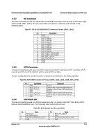
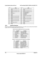
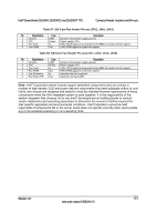
Intel® Server Boards S5520HC, S5500HCV, and S5520HCT TPS Connector/Header Locations and Pin-outs 6.5.6 USB Connector The following table details the pin-out of the external USB connectors (J5A1, J6A1) found on the back edge of the server boards. Table 62. External USB Connector Pin-out (J5A1, J6A1) Pin Signal Name Description 1 USB_OC_5VSB USB_PWR 2 USB_PN DATAL0 (Differential data line paired with DATAH0) 3 USB_PP DATAH0 (Differential data line paired with DATAL0) 4 GND Ground Two 2x5 connectors on the server boards (J1D1, J1D2) provide support for four additional USB ports. J1D2 is recommended for front panel USB ports. Table 63. Internal USB Connector Pin-out (J1D1) Pin Signal Name 1 USB_PWR45_5V 2 USB_PWR45_5V 3 USB_ICH_P4N_CONN 4 USB_ICH_P5N_CONN 5 USB_ICH_P4P_CONN 6 USB_ICH_P5P_CONN 7 Ground 8 Ground 9 Key 10 TP_USB_ICH_NC Description USB power (port 4) USB power (port 5) USB port 4 negative signal USB port 5 negative signal USB port 4 positive signal USB port 5 positive signal No pin Test point Table 64. Internal USB Connector Pin-out (J1D2) Pin Signal Name 1 USB_PWR68_5VSB 2 USB_PWR68_5VSB 3 USB_ICH_P6N_CONN 4 USB_ICH_P8N_CONN 5 USB_ICH_P6P_CONN 6 USB_ICH_P8P_CONN 7 Ground 8 Ground 9 Key 10 TP_USB_ICH_NC Description USB power (port 6) USB power (port 8) USB port 6 negative signal USB port 8 negative signal USB port 6 positive signal USB port 8 positive signal No pin Test point One low-profile 2x5 connector (J2D2) on the server boards provides an option to support a lowprofile USB Solid State Drive. Revision 1.8 115 Intel order number E39529-013
-
 1
1 -
2
-
3
-
4
-
5
-
6
-
7
-
8
-
9
-
10
-
11
-
12
-
13
-
14
-
15
-
16
-
17
-
18
-
19
-
20
-
21
-
22
-
23
-
24
-
25
-
26
-
27
-
28
-
29
-
30
-
31
-
32
-
33
-
34
-
35
-
36
-
37
-
38
-
39
-
40
-
41
-
42
-
43
-
44
-
45
-
46
-
47
-
48
-
49
-
50
-
51
-
52
-
53
-
54
-
55
-
56
-
57
-
58
-
59
-
60
-
61
-
62
-
63
-
64
-
65
-
66
-
67
-
68
-
69
-
70
-
71
-
72
-
73
-
74
-
75
-
76
-
77
-
78
-
79
-
80
-
81
-
82
-
83
-
84
-
85
-
86
-
87
-
88
-
89
-
90
-
91
-
92
-
93
-
94
-
95
-
96
-
97
-
98
-
99
-
100
-
101
-
102
-
103
-
104
-
105
-
106
-
107
-
108
-
109
-
110
-
111
-
112
-
113
-
114
-
115
-
116
-
117
-
118
-
119
-
120
-
121
-
122
-
123
-
 124
124 -
 125
125 -
 126
126 -
 127
127 -
 128
128 -
 129
129 -
 130
130 -
 131
131 -
 132
132 -
 133
133 -
 134
134 -
135
-
136
-
137
-
138
-
139
-
140
-
141
-
142
-
143
-
144
-
145
-
146
-
147
-
148
-
149
-
150
-
151
-
152
-
153
-
154
-
155
-
156
-
157
-
158
-
159
-
160
-
161
-
162
-
163
-
164
-
165
-
166
-
167
-
168
-
169
-
170
-
171
-
172
-
173
-
174
-
175
-
176
-
177
-
178
-
179
-
180
-
181
-
182
-
183
-
184
-
185
-
186
-
187
-
188
-
189
-
190
 |
 |
